This thread has been locked.

If you have a related question, please click the "Ask a related question" button in the top right corner. The newly created question will be automatically linked to this question.

Compiler/ADC141S626: Issue capturing full 14 bits over SPI

Part Number: ADC141S626

Tool/software: TI C/C++ Compiler

Hello,

I am having an issue capturing all 14 bits over spi using the wiringPiSpi Library.
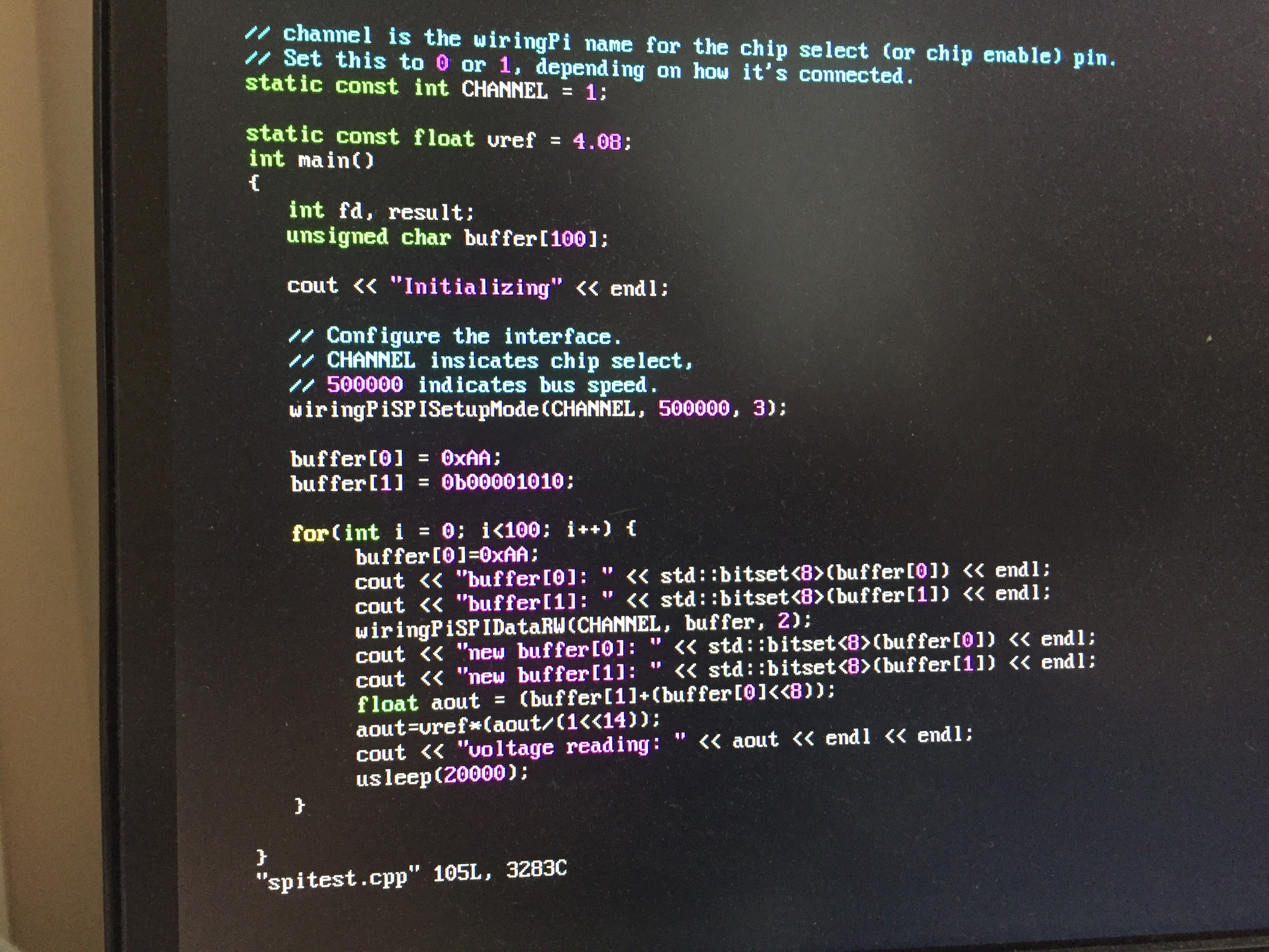
Here is my code:

here are the oscope readings (Yellow: CS, Blue: Sent bits, DarkBlue: Clock, Purple; received bits)

P.S. The vin is tied to vref so i should be getting 0011 1111 1111 1111 incoming.

P.S.S. it seems that the adc is looking for 1 more clock cycle but non of the mode (0-3) have worked. And it seems mode 3 is the closest to what the datasheet wants.

And here is what I am reading in on the Pi:

Let me know what you think,

 And thanks in advance!

Best,

-Danny

  • Also the voltage reading should be 4.08, instead its half of that because the MSB is missing.
  • Hi Danny!

    Can you tell us what code you get when you short the inputs and again when you apply FS- to the inputs? Do they match up with Figure 38 in the ADC141S626 datasheet?
  • What does applying FS- mean?
    I'll assume that means Full Scale Negative. In my particular circuit does this mean negative voltage?

  • Hi Danny,

    Thank's for the schematic! Yes, FS- is 'full scale negative', but you can't actually take the inputs more that 300mV below ground (see page 3). Also, take a look at figures 39-42, these show the typical way to provide an analog input signal to the ADC141S626. Also, take notice of the paragraph on page 15 under Differential Input Operation - the ADC141S626 data is output in Binary 2's compliment, so a full scale positive input will get you hex code 0x1FFF on the digital output pin. In your current configuration, you will never be able to get a FS- output code since you tied IN- to GND. If you connect your external signal to IN+ with IN- tied to a fixed 2.5V DC source, you can swing IN+ from 0-5V. At 0V in, you should see an output code of 0x2000. With IN+ at 2.5V, you should see 0x3FFF - 0x0000, and at 5V you will be back to the 0x1FFF code you are getting now. If you want to have the output in straight binary format, you can 'XOR' the data with 0x2000.