This thread has been locked.

If you have a related question, please click the "Ask a related question" button in the top right corner. The newly created question will be automatically linked to this question.

DAC8531: DAC8531

Part Number: DAC8531

Hello,

I'm trying to interface DAC8531 with Arduino Mega  trough three-wire serial interface (SPI).I've done all the connections and the  skech in ARDUINO IDE to write a value between 0 and 65535 (the input shift register of the DAC is 24 bits wide,  the first six bits are “don’t cares”, the next two bits (PD1 and PD0) are control bits, the next 16 bits are the data bits-these are transferred to the DAC register on the 24th falling edge of SCLK.)

The program is:

#include <SPI.h>

int CS = 53;    //pin53 slave select
int Data = 51;  //pin51 MOSI serial data
int SCLK = 52;   //pin52 clock


void setup() {
  // put your setup code here, to run once:
 
pinMode(CS,OUTPUT);
pinMode(Data,OUTPUT);
pinMode(SCLK,OUTPUT);

SPI.begin();
digitalWrite(CS,HIGH);
SPI.beginTransaction (SPISettings (2000000, MSBFIRST, SPI_MODE1));
delayMicroseconds(1);
}

void loop() {
  // put your main code here, to run repeatedly:
  DAC_Write(2622); // set dac to ~200mV
  delay(3000);

}

void DAC_Write(uint16_t outputValue){
 
byte command=B00000000;
digitalWrite(CS,LOW);
SPI.transfer(command);
SPI.transfer(highByte(outputValue));
SPI.transfer(lowByte(outputValue));
delayMicroseconds(1);
digitalWrite(CS,HIGH);
delayMicroseconds(1);
SPI.endTransaction ();

}

The program it's not working, Arduino's µc it's not writing in the DAC buffer, i don't know if SPI settings are correct or if everything else is in order.

Here is the link for the datasheet of the DAC  : http://www.ti.com/lit/ds/sbas192b/sbas192b.pdf

If someone has worked with this DAC, i would appreciate a few opinions and a little help if possible. Thanks a lot.

  • Hi Dumitry,

    Welcome to E2E and thank you for your query. I am looking into your issue. Could you please provide few scope shots of the SPI waveform in the meanwhile so that we can know whether the interface is actually getting configured properly or not.

    Regards,
    Uttam Sahu
    Applications Engineer, Precision DACs
  • Hi Uttam,

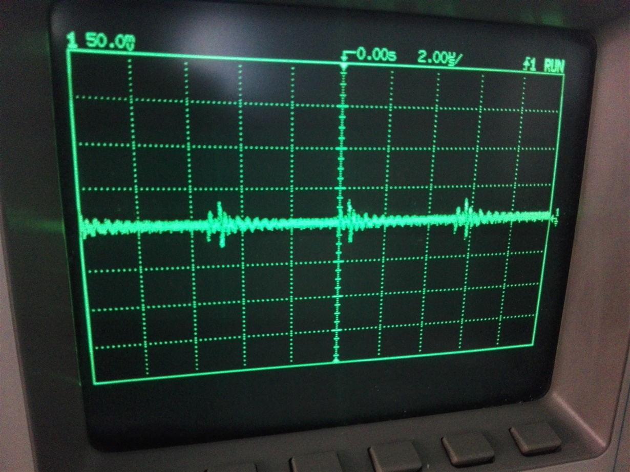
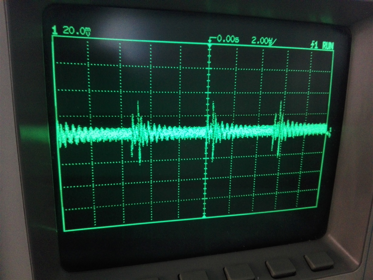
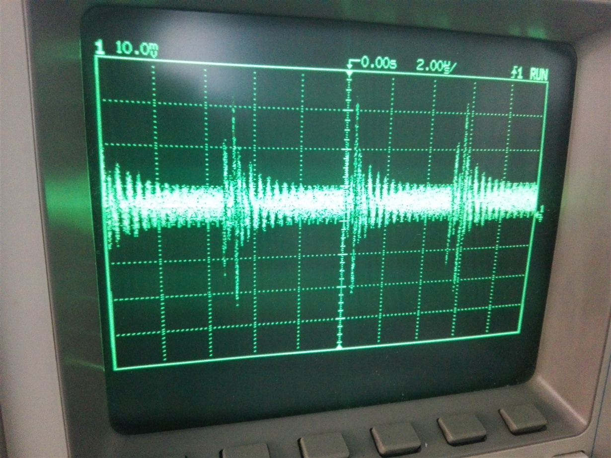
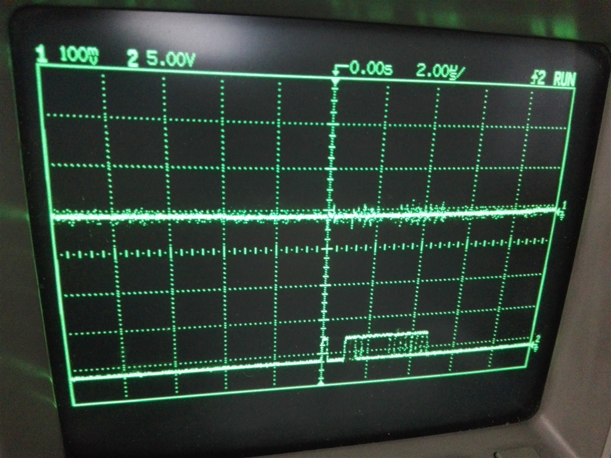
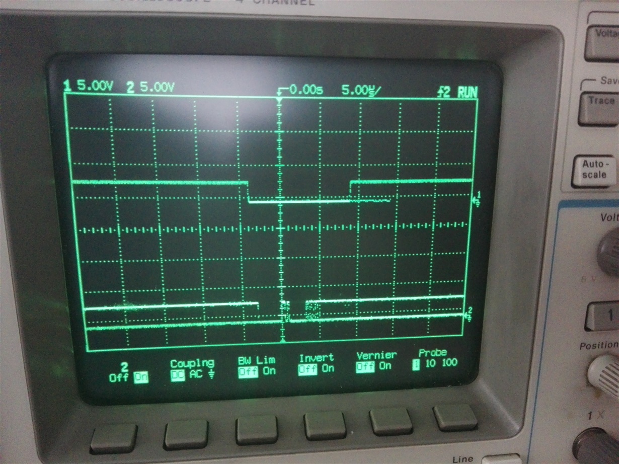
    Thanks for your help.This is the scope:

    The communication with Arduino Mega it's made through pins:

    D51 MOSI- 7 DIN

    D52 SCK- 6 SCLK

    D53 SS- 5 SYNC

    Thank you.

  • Hi Dumitru,

    I am not able to make out any logic pattern from the scope shots. looks like the signals are not properly reaching the DAC. Please check the connections and see if the signals are fine or not.

    Regards,
    Uttam
  • Hi Uttam,

    I tried everything. If you could help me with a schematics connection between Arduino Uno / Mega and DAC8531 and an example of the sketch program to send  data to the DAC,  would be great.I tried all SPI Modes(0, 1, 2, 3), different speeds of communication, and data Order(MSBFIRST or LSBFIRST).In the datasheet is not an example of connections between Arduino and DAC8531.Thank you.Have a good day.

  • Hello,

    I have an update of the program:

    #include "SPI.h"

    int dacCSpin = 53, i;
    byte data1 = 0, data2 = 0;


    void setup() {
      pinMode(dacCSpin, OUTPUT);
      SPI.begin();
      SPI.setBitOrder(MSBFIRST);
      SPI.setDataMode(SPI_MODE1);
    }

    void loop() {

      for ( i = 0; i < 65355; i = i + 10) {
        data1 = highByte(i);
        data2 = lowByte(i);
       
        digitalWrite(dacCSpin, LOW);
        SPI.transfer(0b00000000);
        SPI.transfer(data1);
        SPI.transfer(data2);
        digitalWrite(dacCSpin, HIGH);
       
        Serial.print("sent to DAC: ");
        Serial.print(i);
        Serial.print("     in binary: ");
        Serial.println(i, BIN);
        Serial.println("      ");
      }
      delay (11000);
    }


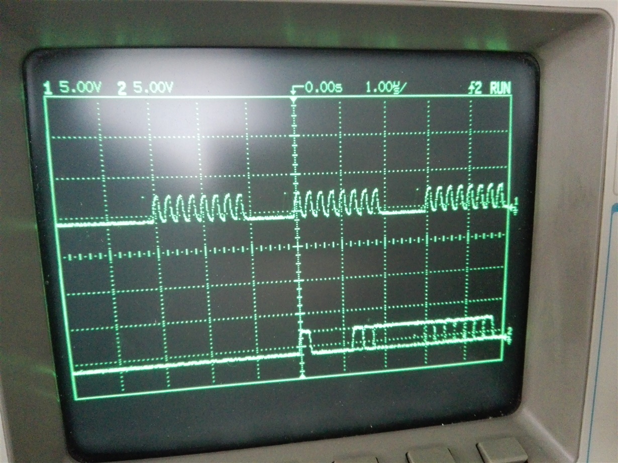
    With this program I can see on the oscilloscope the three SPI signals that Arduino initiates but still can not write anything in the memory of the DAC.

    SPI CLOCK with SPI MOSI

    Vout DAC with SPI MOSI

    SPI SS-SPI MOSI

    What is Vref minimum value?

    An advice would be most appreciate.

    Thank you.

  • Hi Dumitru,

    My apologies for being unresponsive. Did you find any solution to the issue?

    The Vref-min for this device is 0V.

    I am not able to interpret much out the SPI pattern as the overlapping is not clear. It would be good if you could use some mark-ups on the scope shots and show the transitions with zoomed-in view.

    Regards,
    Uttam
  • Dumitru,

    Are you using the EVM in this effort or is this a design of your own? If its your own design, could you also provide a schematic? Apologies if this was already mentioned and I missed it.

    Otherwise, do you have any updates since your last post?