This thread has been locked.

If you have a related question, please click the "Ask a related question" button in the top right corner. The newly created question will be automatically linked to this question.

LDC1000EVM: Setting Rpmin and Rpmax

Part Number: LDC1000EVM
Other Parts Discussed in Thread: LDC1101, LDC1614

I had earlier installed gui 1.0.4.1 version which was not supporting the change of Rp value for finding out the optimal Rpmin and Rpmax values like in the empirical procedure. I kept the Rpmin and Rpmax values at 3F and 0 respectively and reduced it step by step. There is no change observed in the rp values (Do we need to see the blue coloured toggle markers on the proximity data screen or the average value displayed above for 20000-30000 counts while setting Rpmax) ?

Then I tried out using the sensing solutions software. Where is the option for setting the capacitance value? I couldnt find it. Also, how do I set the rpmin and rpmax values here? The output here has a lot of spikes even on plugging in the coil given with the evm. 

  • Hi Deepa,

    Are you referring to the capacitor value in the LC tank? This can be set in the Configuration tab of the Sensing Solutions GUI, in the Configure Inductance Measurements section under Sensor Parameters. You can change Rpmin and Rpmax in the Configure Rp Measurements and Comparator section under Rp Configuration.

    If you are seeing spikes on your output, this is often caused by EMI. Try to remove the EVM from the vicinity of potentially aggressive signals and any long cables. The spikes should not be caused by incorrect Rpmin/max settings. In fact, the measured Rp will be held at an incorrect value, so the resulting output waveform would be more constant than when Rp is being correctly measured.

    Regards,
  • Are you saying that even if rpmin and rpmax values are incorrect, it would not cause spikes in the output?

    I am using a custom coil and my capacitor is 100000pf ( 100nf). I set the capacitor value and tried configuring rpmin and rpmax values by setting  to 0 and 3F and increasing and reducing based on the proximity data value. But the proximity data does not go down to 0 or even change significantly when i try changing the rpmin and rpmax values for finding out the optimal settings. The empirical procedure of finding rpmin and rpmax is not working for me. Is there anything else i can do? And also, i don't have an impedance analyser available with me for testing.

  • Also, my inductor (rectangular loop) value (along with the 5m cable that extends from the loop) is around 100uH. After a trial and error kind of testing, I got rpmin around 4kohm and rpmax along 700kohm.

    1. I there anyway that I can verify these values?

    For these values, the spikes seem to have reduced but the detection of metal target takes around 50seconds to respond i.e it takes nearly 50seconds to show the difference on the screen.

    2. What is minimum required time delay between simultaneous targets?

    3. Also, upto what height of target can it detect?

    4. Is using a capacitance of 100000pf okay?

  • Hi Deepa,

    1. You can verify Rpmin and Rpmax by following the instructions on page 24 of the datasheet. I strongly recommend using an impedance analyzer to verify the measured Rp value of your coil, but there are alternatives. Try this app note for other options that you may be able to do in your lab:

    http://www.ti.com/lit/an/snoa936/snoa936.pdf

    2. The 50 second delay you are seeing is likely caused by a known GUI issue where the program will sometimes momentarily freeze. It does not happen on all computers, so we have not been able to solve this bug yet. In any case, the GUI is not graphing every sample captured by the LDC1000. The maximum sample frequency is determined by the sensor frequency and the RESPONSE_TIME register. See section 8.1.2 of the datasheet for the equation to calculate sample rate.

    3. The detection distance is based on the RESPONSE_TIME settings and the smallest diameter of the coil. I recommend reading these two application notes:

    LDC Sensor Design

    LDC Target Design

    4. I would suggest using a smaller capacitor. With the 100uH inductor, a 100nF capacitor will yield a sensor frequency of about 50kHz. You will be able to sample faster if you use a smaller capacitor (and therefore a higher sensor frequency). In addition, higher frequencies reduce the skin depth of the target, which can yield a stronger response in thin targets. See the app notes above for more details about skin depth.

    Regards,

  • Hi Kristen,

    Thanks for all your help. We were able to complete the setup and although inductance was showing response with spikes, it was detecting metal. But we are still facing some issues. Let me explain the application. 

    We require a setup that would let us identify the vehicles that pass on the road (Inductive loop vehicle detector). As mentioned before, the inductance of the coil along with the wire is coming out to be 100uF. The capacitance we used is still 100nF (I tried using a capacitor of lower value but the gui showed no response to metal). We require that the vehicle that pass over the loop provide different waveforms depending on their type (As vehicles such as car, bus all have different metal content at different portions).

    With the current setup, we were not getting good signatures for vehicles. Also, the loop is not responding for all the vehicles. It is missing out majority of vehicles especially bus which might be due to its height (distance from the loop is greater). And it is able to detect only those vehicles which pass over slowly. 

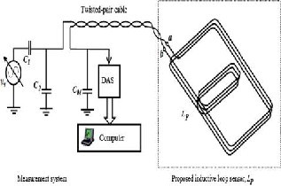
    Our coil structure is as shown in figure

    For solving these issues, will it be better if we go for some higher version of LDC? Currently we are using LDC1000EVM with sensing solutions gui. Can you suggest any way to get a better output for this application? 

    Can LDC not be used for dynamic applications?

  • Hi Deepa,

    I do think you will need to use a more sensitive device for this application. I would recommend either the LDC1101 or the LDC161x. 

    I think there are two main challenges with this application:

    1) The smoother the target, the stronger the response. This is because the eddy currents in the target must flow in closed loops, and will be forced to flow around any gaps or discontinuities in the target. This mismatch between the shape of the inductor current path and the target current path will decrease the coupling between the two, which results in a smaller measured inductance shift. The undercarriage of vehicles will have many discontinuities, which could make a strong response challenging. 

    2) The detection distance is based on the smallest diameter of the sensor coil. Generally the detection distance is about 100% of the coil diameter, but for high resolution parts (like the LDC1614 and LDC1101) can be as much as 200% of the coil diameter. It could be challenging to create a coil large enough to meet the target distance requirements and still meet the Rp requirements so the LDC device can drive the LC tank. 

    Also, could you clarify the connections in your figure? I don't see a capacitor in parallel with the sensor inductor. Are the other capacitors for ESD concerns?

    Regards,