This thread has been locked.

If you have a related question, please click the "Ask a related question" button in the top right corner. The newly created question will be automatically linked to this question.

ADS8694: SPI Communication with the ADS8694 18bit ADC and the TMS320F28379D Launchpad

Part Number: ADS8694
Other Parts Discussed in Thread: TMS320F28379D

Dear all,

I am still having problems to use SPI with the ADS8694.

If I use GPIOs without the SPI, the ADC responds to all my commands and sends results back. All the signals are there as they should.

However, if I use the same pins under SPI, I can only get the buffer full of 1's

I control the SPISTE signal separately, and I am by now not using DMA.

If I choice SpiaRegs.SPICCR.bit.SPILBK = 1, everything comes and go as I want. If it is = 0, I get only 1's back by every command I send, it doesen't matter which one.

Saddly, I am on travel and have no access to an oscilloscope to check if the clock is working as needed, but  a software check from SPISTE shows that it is doing the job.

Attached is the relevant part of my code.

As always, many thanks for your help!

Best regards,

Gustavo

forTi10092018.c
#include "F28x_Project.h"

//
// Function Prototypes
//
void spi_fifo_init(void);
void InitSpi(void);
void InitSpiaGpio();

Uint16 Cmd0,Cmd1,Cmd2,Cmd3,Cmd4,CmdDummy,CmdDummy8,Cmd5;
Uint16 i,CSstate;
Uint32 rdata;  // received data

void main(void)
{

// Initialize System Control:
   InitSysCtrl();

// Initialize GPIO:
   InitSpiaGpio();

// Clear all interrupts:
   DINT;

// Initialize PIE control registers to their default state.
   InitPieCtrl();

// Disable CPU __interrupts and clear all CPU __interrupt flags:
   IER = 0x0000;
   IFR = 0x0000;

// Initialize the PIE vector table with pointers to the shell Interrupt
// Service Routines (ISR).
   InitPieVectTable();

// Initialize the Device Peripherals:
   spi_fifo_init();     // Initialize the SPI FIFO

//  User specific code:

    Cmd0 = 0b1000010100000000; 										// Reset program registers (RST) (1000 0101 00000000)
    Cmd1 = 0b0000101100000110;										// WRITE Channel 0 Input Range. I need 0x0110 (0000 101 1 00000110)
    Cmd2 = 0b0000101000000000;										// READ range channel 0	(0000 101 0 00000000)
    Cmd3 = 0b1100000000000000; 										// Manual Channel n Select (MAN_Ch_0) (1100 0000 00000000)
    Cmd4 = 0b0000000000000000; 										// continue with last config (0000 0000 00000000)
		CmdDummy = 101010101010101001;
		CmdDummy8 = 10101011;

// send data

    	 GpioDataRegs.GPBCLEAR.bit.GPIO61 = 1;							// set CS Low to start transmission

       while(SpiaRegs.SPISTS.bit.BUFFULL_FLAG !=0) { }
       SpiaRegs.SPITXBUF = Cmd0;  												// send one 16 bit command
       while(SpiaRegs.SPIFFRX.bit.RXFFST !=1) { }  				// Wait until data is received
       rdata = SpiaRegs.SPIRXBUF;
       while(SpiaRegs.SPISTS.bit.BUFFULL_FLAG !=0) { }
       SpiaRegs.SPITXBUF = CmdDummy;  										// send 18 bits dummy
       while(SpiaRegs.SPIFFRX.bit.RXFFST !=1) { }  				// Wait until data is received
       rdata = SpiaRegs.SPIRXBUF;

// Arrange data
       rdata = rdata << 16;
       rdata = rdata |  SpiaRegs.SPIRXBUF;
       rdata = rdata << 16;
       rdata = rdata >> 16;    														// use only the last 16 bits received
       
       GpioDataRegs.GPBSET.bit.GPIO61 = 1;         				// set CS high to end transmission
ESTOP0;
   
}

//
// END of MAIN
//


//
// spi_fifo_init - Initialize SPIA FIFO
//
void spi_fifo_init()
{
    //
    // Initialize SPI FIFO registers
    //
    SpiaRegs.SPIFFTX.all = 0xE040;
    SpiaRegs.SPIFFRX.all = 0x2044;
    SpiaRegs.SPIFFCT.all = 0x0;

    //
    // Initialize core SPI registers
    //
    InitSpi();
}
void InitSpi(void)
{
    SpiaRegs.SPICCR.bit.SPISWRESET = 0;
    SpiaRegs.SPICCR.bit.CLKPOLARITY = 0;
    SpiaRegs.SPICCR.bit.SPICHAR = 15;
    SpiaRegs.SPICCR.bit.SPILBK = 0;
    SpiaRegs.SPICTL.bit.MASTER_SLAVE = 1;
    SpiaRegs.SPICTL.bit.TALK = 1;
    SpiaRegs.SPICTL.bit.CLK_PHASE = 0;
    SpiaRegs.SPICTL.bit.SPIINTENA = 0;
    SpiaRegs.SPIBRR.bit.SPI_BIT_RATE = SPI_BRR;
    SpiaRegs.SPIPRI.bit.FREE = 1;
    SpiaRegs.SPICCR.bit.SPISWRESET = 1;
}

void InitSpiaGpio()
{
   EALLOW;
    // Enable internal pull-up for the selected pins
    GpioCtrlRegs.GPBPUD.bit.GPIO58 = 0;  // Enable pull-up on GPIO58 (SPISIMOA)
    GpioCtrlRegs.GPBPUD.bit.GPIO59 = 0;  // Enable pull-up on GPIO59 (SPISOMIA)
    GpioCtrlRegs.GPBPUD.bit.GPIO60 = 0;  // Enable pull-up on GPIO60 (SPICLKA)
    GpioCtrlRegs.GPAPUD.bit.GPIO19 = 0;  // Enable pull-up on GPIO19 (dummy SPISTEA)

    // Set qualification for selected pins to asynch only
    GpioCtrlRegs.GPBQSEL2.bit.GPIO58 = 3; // Asynch input GPIO58 (SPISIMOA)  
    GpioCtrlRegs.GPBQSEL2.bit.GPIO59 = 3; // Asynch input GPIO59 (SPISOMIA)
    GpioCtrlRegs.GPBQSEL2.bit.GPIO60 = 3; // Asynch input GPIO60 (SPICLKA)
    GpioCtrlRegs.GPAQSEL2.bit.GPIO19 = 3; // Asynch input GPIO19 (dummy SPISTEA)

    //Configure SPI-A pins using GPIO regs
    GpioCtrlRegs.GPBMUX2.bit.GPIO58 = 1; // Configure GPIO58 as SPISIMOA
    GpioCtrlRegs.GPBMUX2.bit.GPIO59 = 1; // Configure GPIO59 as SPISOMIA
    GpioCtrlRegs.GPBMUX2.bit.GPIO60 = 1; // Configure GPIO60 as SPICLKA
    GpioCtrlRegs.GPAMUX2.bit.GPIO19 = 1; // Configure GPIO19 as dummy SPISTEA

    GpioCtrlRegs.GPBGMUX2.bit.GPIO61 = 0; // GPIO61 = GPIO61 (software controlled SPISTEA)
    GpioCtrlRegs.GPBMUX2.bit.GPIO61 = 0;  // GPIO61 = GPIO61 (software controlled SPISTEA)
    GpioCtrlRegs.GPBPUD.bit.GPIO61 = 0;  	// Enable pull-up on GPIO61 (software controlled SPISTEA)
    GpioCtrlRegs.GPBDIR.bit.GPIO61 = 1;		// configure GPIO61 as OUTPUT (software controlled SPISTEA)

    // use GPIO111 as the reset pin for the ADS8694.
    GpioCtrlRegs.GPDGMUX1.bit.GPIO111 = 0; // GPIO111 = GPIO111
    GpioCtrlRegs.GPDMUX1.bit.GPIO111 = 0;  // GPIO111 = GPIO111
    GpioCtrlRegs.GPDDIR.bit.GPIO111 = 1;   // configure GPIO111 as OUTPUT
    GpioCtrlRegs.GPDPUD.bit.GPIO111 = 0;   // Enable pull-up on GPIO111 (RST)
    GpioDataRegs.GPDSET.bit.GPIO111 = 1;   // Set GPIO111 HIGH !!!! to activate ADS8694
    
   EDIS;
}

  • Hello Gustavo,

    I noticed that you had a similar post (SPI interface, goes well for loopback, but get all ones on the SDO line for 'real life') on C2000 forum in Aug, it was marked with "solved", can you please help us understand the difference well? is your attached c file exactly same for your both tests only except pin definition to GPIOs or standard SPI pins on same physical pins? It's better for us to check timing plots for both tests(GPIO and SPI pins) with an oscilloscope.

    e2e.ti.com/.../719946

    Thanks&regards

    Dale

  • Hi Dale,
    thanks for your quick response.

    Let me try to explain it:
    The other post was solved, because I suceeded to get the ADC responding by using a routine replacing spi (see the attached file "forTi-Brute-Force-11092018.c") using the same pins I would use for SPI as normal GPIOs controlled by my software.
    So I was making my own CLK signal toogling pin 60, sending my data setting or clearing pin 58 (SDI) and reading the state of pin 59 (SDO) to get the bits from the ADC.
    Everything works fine.

    The difference now, as you noticed, is that I have the same pins configured for SPI, with the exception of SPISTE, which I am still controlling by software, to be sure, it goes low for the whole frame. And, instead of setting or clearing pin 58, I am writing to SPITXBUF, as you do in the example I got in August.

    As soon as I send a command, the ADC gives back 1´s on SDO. The Data Sheet says, this should be 0´s
    No valid information at all is coming back from the ADC.

    I think the timing is as it should be, but I am pretty sure, I am missing something. We have checked this in a team and could not find any reason for this.

    The Baudrate is low enough: #define SPI_BRR ((200E6 / 4) / 500E3) - 1

    I need SPI, and also DMA, because the application is time sensitive, so I cannot keep the processor bussy by toogling a clock signal.

    I could use one of the PWMs to generate a clock and interrupts, but by a powerful processor as the TMS320F28379D this seems to be a shame.

    I have no plots, saddly. I am on travel and get no access to an oscilloscope till next week, but, anyway, my means are limited to see things happen on the screen, or checking it with variables and breakpoints.

    I am sure, CS goes low or high as it should, RST is high, lopback works. Only the CLK line I cannot test.

    So the big question is: why is SDO always high? I checked also not allowing pullup in SDO (pin59), but the result is the same.

    I include the whole file with the spi code, plus the file with the inits for the spi and gpios, as they are now. Sorry for the mess. (Lots of test variables and breakpoints there)
    I hope, this is not too confusing...
    Thanks and best regards,
    Gustavo (today in Warsaw)
    forTi-Brute-Force-11092018.c
    #include "F28x_Project.h"     
    
    // Function Prototypes
    void delay_loop(void);
    void initSerialPins(void);
    void ADS8694_CMD(Uint16 a, Uint16 clkCycles);
    void WriteReadConfigADC18(Uint16 a, Uint16 clkCycles);
    
    Uint16 Cmd0,Cmd1,Cmd2,Cmd3,Cmd4,Cmd5;
    Uint16 r,a,b,i,j,k,y,z,CSstate;
    
    Uint32 rdataADC;
    
    void main(void)
    {
        // Initialize GPIO
        InitGpio(); 
    
        // Clear all interrupts and initialize PIE vector table
        DINT;
        InitPieCtrl();
    
        IER = 0x0000;
        IFR = 0x0000;
    
        InitPieVectTable();
    
        initSerialPins();												// This function uses the spi pins to imitate it
    
        GpioDataRegs.GPBSET.bit.GPIO61 = 1;								// set CS high
        delay_loop();
    
        CSstate = GpioDataRegs.GPBDAT.bit.GPIO61;						// check CS state
    
        Cmd0 = 0b10000101; 										// Reset program registers (RST) (1000 0101 00000000)
        Cmd1 = 0b11000000; 										// Manual Channel n Select (MAN_Ch_0) (1100 0000 00000000)
        Cmd2 = 0b00000000; 										// continue with last config (0000 0000 00000000)
        Cmd3 = 0b0000101100000110;										// WRITE Channel 0 Input Range. I need 0x0110 (0000 101 1 00000110)
        Cmd4 = 0b0000101000000000;										// READ range channel 0	(0000 101 0 00000000)
        
        //Uncomment only what is to be sent to the ADC
        ESTOP0;
    
    	ADS8694_CMD(Cmd0,33);											//	Reset program registers (0b10000101)
    
        ESTOP0;
        WriteReadConfigADC18(Cmd3,23);										// WRITE Range Ch0 (MAN_Ch_0) 0b1000001011010011 (0b01011011) (dec 11) 0110 = Input range is set to 0 to 1.25 x VREF
    
        ESTOP0;
        WriteReadConfigADC18(Cmd4,23);										// READ Range Ch0 (MAN_Ch_0) (0b00001010) (dec 10)
        
        ESTOP0;
    		ADS8694_CMD(Cmd1,33);											// Manual Channel n Select (MAN_Ch_0) (0b11000000)
    
    //continue to convert forever
    	    ESTOP0;
       for (;;) 
        {
        	ADS8694_CMD(Cmd2,33);		// now measure channel 0 in loop.
            ESTOP0;
        }
    	
    
    }
    // END of main()
    
    
    void ADS8694_CMD(Uint16 a, Uint16 clkCycles)
    {
        rdataADC = 0;
        GpioDataRegs.GPBSET.bit.GPIO60 = 1;							// set clk AHigh to begin swapping with a known position
        delay_loop();
        GpioDataRegs.GPBCLEAR.bit.GPIO61 = 1;							// set CS Low to start transmission    
    		delay_loop();
        
        for(i=0;i<8;i++)    											//Send CMD 8bit
        {        
            if(a &  0b10000000)        									
                GpioDataRegs.GPBSET.bit.GPIO58 = 1;
            else
                GpioDataRegs.GPBCLEAR.bit.GPIO58 = 1;
            
            GpioDataRegs.GPBTOGGLE.bit.GPIO60 = 1;    					// SCLK LOW - ADC reads bit
            delay_loop();
    
            GpioDataRegs.GPBTOGGLE.bit.GPIO60 = 1;     					// SCLK HIGH
            delay_loop();
            
            a = a << 1;	
        }
        
        r=0;
        GpioDataRegs.GPBCLEAR.bit.GPIO58 = 1 ;         					// Put SPISIMO low for the rest of the time
        
        for(i=8;i<16;i++)    											//Send the next eight bits = 0
        {
            GpioDataRegs.GPBTOGGLE.bit.GPIO60 = 1;    					// SCLK LOW - ADC reads bit
            delay_loop();
            GpioDataRegs.GPBTOGGLE.bit.GPIO60 = 1;     					// SCLK HI
            delay_loop();
        }
           
    		// 16 falling edges
        // At the 16th falling edge of the SCLK signal, (already happened)
        // the MSB of the conversion data is output on the SDO line and can be read by the host processor on the subsequent (17) falling edge of the SCLK signal.
    
        GpioDataRegs.GPBTOGGLE.bit.GPIO60 = 1;    						// SCLK LOW 17th falling edge (now we can read the MSB of the ADC18
        delay_loop();
    
        if(GpioDataRegs.GPBDAT.bit.GPIO59 == 1)							//Check SDO 1 or 0 (read MSB of 8 bits ADC config)
            rdataADC = 1;
        else
            rdataADC = 0;
            
        GpioDataRegs.GPBTOGGLE.bit.GPIO60 = 1;    						// SCLK HI
        delay_loop();
    
        // continue with bits 18 - 0
        for(i=16;i<clkCycles;i++)
        {
            GpioDataRegs.GPBTOGGLE.bit.GPIO60 = 1;    					// SCLK LOW
            delay_loop();
    
            if(GpioDataRegs.GPBDAT.bit.GPIO59 == 1)						//Check SDO 1 or 0
                r = 1;
            else
                r = 0;
            rdataADC = rdataADC << 1; 									// make 8 or 18 bits from received data	    MSB received first
            rdataADC = rdataADC | r; 									// make 8 or 18 bits from received data	    MSB received first
            
            GpioDataRegs.GPBTOGGLE.bit.GPIO60 = 1;    					// SCLK HI
            delay_loop();
        }
    
        GpioDataRegs.GPBCLEAR.bit.GPIO60 = 1;							// set clk low make sure, transmission stops
        if(GpioDataRegs.GPBDAT.bit.GPIO59 == 1)							//Check SDO for the last time (never know)
            r = 1;
        else
            r = 0;
    
        GpioDataRegs.GPBSET.bit.GPIO61 = 1;								// set CS high to end transmission
    	return;
    }
    
    void WriteReadConfigADC18(Uint16 a, Uint16 clkCycles)
    {
        rdataADC = 0;
        GpioDataRegs.GPBSET.bit.GPIO60 = 1;							// set clk High to begin swapping with a known position
        delay_loop();
        GpioDataRegs.GPBCLEAR.bit.GPIO61 = 1;							// set CS Low to start transmission
        delay_loop();
    
        for(i=0;i<16;i++)    											//Send CMD 16bit
        {        
            if(a &  0b1000000000000000)        									// if first character of a is a 1
                GpioDataRegs.GPBSET.bit.GPIO58 = 1;
            else
                GpioDataRegs.GPBCLEAR.bit.GPIO58 = 1;
            
            GpioDataRegs.GPBTOGGLE.bit.GPIO60 = 1;    					// SCLK LOW - ADC reads bit
            delay_loop();
    
            GpioDataRegs.GPBTOGGLE.bit.GPIO60 = 1;     					// SCLK HIGH
            delay_loop();
            
            a = a << 1;													// leftshift. Ej: cmd[0]: 10000101 << 1 = 100001010 (se agregan ceros a la derecha!!!)
        }
    // 16 falling edges
        
        r=0;
        GpioDataRegs.GPBCLEAR.bit.GPIO58 = 1 ;         					// Put SPISIMO low for the rest of the time
    // From the 16th SCLK falling edge and onwards, SDO outputs the 8-bit data from the addressed register during the next eight clocks, in MSB-first fashion	   
    // and can be read by the host processor on the subsequent (17) falling edge of the SCLK signal.
    
        GpioDataRegs.GPBTOGGLE.bit.GPIO60 = 1;    						// SCLK LOW 17th falling edge (now we can read the MSB of the ADC18
        delay_loop();
    
        if(GpioDataRegs.GPBDAT.bit.GPIO59 == 1)							//Check SDO 1 or 0 (read MSB of 8 bits ADC config)
            rdataADC = 1;
        else
            rdataADC = 0;
            
        GpioDataRegs.GPBTOGGLE.bit.GPIO60 = 1;    						// SCLK HI
        delay_loop();
    
        // continue with bits 18 - 0
        for(i=16;i<clkCycles;i++)
        {
            GpioDataRegs.GPBTOGGLE.bit.GPIO60 = 1;    					// SCLK LOW
            delay_loop();
    
            if(GpioDataRegs.GPBDAT.bit.GPIO59 == 1)						//Check SDO 1 or 0
                r = 1;
            else
                r = 0;
            rdataADC = rdataADC << 1; 									// make 8 bits from received data	    MSB received first
            rdataADC = rdataADC | r; 									// make 8 bits from received data	    MSB received first
            
            GpioDataRegs.GPBTOGGLE.bit.GPIO60 = 1;    					// SCLK HI
            delay_loop();
        }
    
        GpioDataRegs.GPBCLEAR.bit.GPIO60 = 1;							// set clk low make sure, transmission stops
        if(GpioDataRegs.GPBDAT.bit.GPIO59 == 1)							//Check SDO for the last time (never know)
            r = 1;
        else
            r = 0;
        GpioDataRegs.GPBSET.bit.GPIO61 = 1;								// set CS high to end transmission
    	return;
    }
    
    // delay_loop - Function to add delay
    //
    void delay_loop()
    {
        long k;
        for (k = 0; k < 10000; k++) {}
    }
    
    
    void initSerialPins()
    {
        EALLOW;
        GpioCtrlRegs.GPBGMUX2.bit.GPIO58 = 0;  						// GPIO58 = GPIO58 (SPISIMOA)
        GpioCtrlRegs.GPBGMUX2.bit.GPIO59 = 0;  						// GPIO59 = GPIO59 (SPISOMIA)
        GpioCtrlRegs.GPBGMUX2.bit.GPIO60 = 0;  						// GPIO60 = GPIO60 (SPICLKA)
        GpioCtrlRegs.GPBGMUX2.bit.GPIO61 = 0;  						// GPIO61 = GPIO61 (SPISTEA)
    
        GpioCtrlRegs.GPBMUX2.bit.GPIO58 = 0;  						// GPIO58 = GPIO58 (SPISIMOA)
        GpioCtrlRegs.GPBMUX2.bit.GPIO59 = 0;  						// GPIO59 = GPIO59 (SPISOMIA)
        GpioCtrlRegs.GPBMUX2.bit.GPIO60 = 0;  						// GPIO60 = GPIO60 (SPICLKA)
        GpioCtrlRegs.GPBMUX2.bit.GPIO61 = 0;  						// GPIO61 = GPIO61 (SPISTEA)
    
        GpioCtrlRegs.GPBPUD.bit.GPIO58 = 0;  						// Enable pull-up on GPIO58 (SPISIMOA)
        GpioCtrlRegs.GPBPUD.bit.GPIO59 = 0;  						// Enable pull-up on GPIO59 (SPISOMIA)
        GpioCtrlRegs.GPBPUD.bit.GPIO60 = 0;  						// Enable pull-up on GPIO60 (SPICLKA)
        GpioCtrlRegs.GPBPUD.bit.GPIO61 = 0;  						// Enable pull-up on GPIO61 (SPISTEA)
    
        GpioCtrlRegs.GPBDIR.bit.GPIO58 = 1;							// configure GPIO58 as OUTPUT (SPISIMOA)
        GpioCtrlRegs.GPBDIR.bit.GPIO59 = 0;							// configure GPIO59 as INPUT  (SPISOMIA)
        GpioCtrlRegs.GPBDIR.bit.GPIO60 = 1;							// configure GPIO60 as OUTPUT (SPICLKA)
        GpioCtrlRegs.GPBDIR.bit.GPIO61 = 1;							// configure GPIO61 as OUTPUT (SPISTEA)
    
        // GPIO111 is used for the Hardware reset of the ADS8694.
        //Must be LOW to activate it
        GpioCtrlRegs.GPDGMUX1.bit.GPIO111 = 0;  					// GPIO111 = GPIO111
        GpioCtrlRegs.GPDMUX1.bit.GPIO111 = 0;  						// GPIO111 = GPIO111
        GpioCtrlRegs.GPDDIR.bit.GPIO111 = 1;						// configure GPIO111 as OUTPUT
        GpioCtrlRegs.GPDPUD.bit.GPIO111 = 0;  						// Enable pull-up on GPIO111 (RST)
        GpioDataRegs.GPDSET.bit.GPIO111 = 1; 						// Set GPIO111 HIGH !!!! to activate ADS8694 
        EDIS;
    }


    forTi-SPI-11092018.c
    // Included Files
    //
    #include "F28x_Project.h"
    
    //
    // Function Prototypes
    //
    void delay_loop(void);
    void spi_xmit(Uint16 a);
    void spi_fifo_init(void);
    void spi_init(void);
    
    Uint16 Cmd0,Cmd1,Cmd2,Cmd3,Cmd4,CmdDummy,CmdDummy8;
    Uint16 r,a,b,i,j,k,y,z,checkpointValue,comandToSend,CSstate,CLKstate,iamhere,written,fallingEdge,measuringNr,RXfifoStatus;
    Uint32 rdata;  // received data
    
    void main(void)
    {
    
       InitSysCtrl();
    
       InitSpiaGpio();
    
       DINT;
    
       InitPieCtrl();
    
       IER = 0x0000;
       IFR = 0x0000;
    
       InitPieVectTable();
    
       spi_fifo_init();     // Initialize the SPI FIFO
    
    //
    // User specific code:
    //
    
        Cmd0 = 0b1000010100000000; 										// Reset program registers (RST) (1000 0101 00000000)
        Cmd1 = 0b0000101100000110;										// WRITE Channel 0 Input Range. I need 0x0110 (0000 101 1 00000110)
        Cmd2 = 0b0000101000000000;										// READ range channel 0	(0000 101 0 00000000)
        Cmd3 = 0b1100000000000000; 										// Manual Channel n Select (MAN_Ch_0) (1100 0000 00000000)
        Cmd4 = 0b0000000000000000; 										// continue with last config (0000 0000 00000000)
    		CmdDummy = 101010101010101001;
    		CmdDummy8 = 10101011;
    
        GpioDataRegs.GPBCLEAR.bit.GPIO61 = 1;							// set CS Low to start transmission
        delay_loop();
        CSstate = GPIO_ReadPin(61);                                     // check CS state
    ESTOP0;
    
       for(;;)
       {
    // send data
    
           while(SpiaRegs.SPISTS.bit.BUFFULL_FLAG !=0) { }
           SpiaRegs.SPITXBUF = Cmd0;  // send 16 bit command // Reset program registers (RST) (1000 0101 00000000)
           while(SpiaRegs.SPIFFRX.bit.RXFFST !=1) { }  // Wait until data is received
           rdata = SpiaRegs.SPIRXBUF;
    ESTOP0;
           while(SpiaRegs.SPISTS.bit.BUFFULL_FLAG !=0) { }
           SpiaRegs.SPITXBUF = CmdDummy;  // send 18 bits dummy
           while(SpiaRegs.SPIFFRX.bit.RXFFST !=1) { }  // Wait until data is received
           rdata = SpiaRegs.SPIRXBUF;
            GpioDataRegs.GPBSET.bit.GPIO61 = 1;         // set CS high to end transmission
            delay_loop();
            CSstate = GPIO_ReadPin(61);                 // check CS state
           spi_fifo_init();    // ver si es necesario
    ESTOP0;
               rdata = 0;  // clear data
        GpioDataRegs.GPBCLEAR.bit.GPIO61 = 1;							// set CS Low to start transmission
        delay_loop();
        CSstate = GPIO_ReadPin(61);                                     // check CS state
    
           while(SpiaRegs.SPISTS.bit.BUFFULL_FLAG !=0) { }
           SpiaRegs.SPITXBUF = Cmd0;  // send 16 bit command // Reset program registers (RST) (1000 0101 00000000)
           while(SpiaRegs.SPIFFRX.bit.RXFFST !=1) { }  // Wait until data is received
           rdata = SpiaRegs.SPIRXBUF;
    ESTOP0;
           while(SpiaRegs.SPISTS.bit.BUFFULL_FLAG !=0) { }
           SpiaRegs.SPITXBUF = CmdDummy8;  // send 8 bits dummy
           while(SpiaRegs.SPIFFRX.bit.RXFFST !=1) { }  // Wait until data is received
           rdata = SpiaRegs.SPIRXBUF;
            GpioDataRegs.GPBSET.bit.GPIO61 = 1;         // set CS high to end transmission
            delay_loop();
            CSstate = GPIO_ReadPin(61);                 // check CS state
           spi_fifo_init();
    ESTOP0;
           rdata = 0;
        GpioDataRegs.GPBCLEAR.bit.GPIO61 = 1;							// set CS Low to start transmission
        delay_loop();
        CSstate = GPIO_ReadPin(61);                                     // check CS state
    
           while(SpiaRegs.SPISTS.bit.BUFFULL_FLAG !=0) { }
           SpiaRegs.SPITXBUF = Cmd0;  // send 16 bit command // Reset program registers (RST) (1000 0101 00000000)
           while(SpiaRegs.SPIFFRX.bit.RXFFST !=1) { }  // Wait until data is received
           rdata = SpiaRegs.SPIRXBUF;
    ESTOP0;
           while(SpiaRegs.SPISTS.bit.BUFFULL_FLAG !=0) { }
           SpiaRegs.SPITXBUF = CmdDummy8;  // send 8 bits dummy
           while(SpiaRegs.SPIFFRX.bit.RXFFST !=1) { }  // Wait until data is received
           rdata = SpiaRegs.SPIRXBUF;
            GpioDataRegs.GPBSET.bit.GPIO61 = 1;         // set CS high to end transmission
            delay_loop();
            CSstate = GPIO_ReadPin(61);                 // check CS state
           spi_fifo_init();
    ESTOP0;
    // etc.
       } 
    }
    
    //
    // delay_loop - Loop for a brief delay
    //
    void delay_loop()
    {
        long i;
        for (i = 0; i < 1000000; i++) {}
    }
    
    
    //
    // spi_fifo_init - Initialize SPIA FIFO
    //
    void spi_fifo_init()
    {
        //
        // Initialize SPI FIFO registers
        //
        SpiaRegs.SPIFFTX.all = 0xE040;
        SpiaRegs.SPIFFRX.all = 0x2044;
        SpiaRegs.SPIFFCT.all = 0x0;
    
        //
        // Initialize core SPI registers
        //
        InitSpi();
    }
    
    //
    // End of file
    //
    
    forTi-SPI-initSPI-11092018.c
    // Included Files
    //
    #include "F2837xD_device.h"
    #include "F2837xD_Examples.h"
    
    //
    // Calculate BRR: 7-bit baud rate register value
    // SPI CLK freq = 500 kHz
    // LSPCLK freq  = CPU freq / 4  (by default)
    // BRR          = (LSPCLK freq / SPI CLK freq) - 1
    //
    #if CPU_FRQ_200MHZ
    #define SPI_BRR        ((200E6 / 4) / 500E3) - 1
    #endif
    
    #if CPU_FRQ_150MHZ
    #define SPI_BRR        ((150E6 / 4) / 500E3) - 1
    #endif
    
    #if CPU_FRQ_120MHZ
    #define SPI_BRR        ((120E6 / 4) / 500E3) - 1
    #endif
    
    //
    // InitSPI - This function initializes the SPI to a known state
    //
    void InitSpi(void)
    {
        SpiaRegs.SPICCR.bit.HS_MODE = 0;        // if = 0, High speed not used. This is because I use the pins for high speed spi and they are not working without this
    
        SpiaRegs.SPICCR.bit.SPISWRESET = 0;
        SpiaRegs.SPICCR.bit.CLKPOLARITY = 0;
        SpiaRegs.SPICCR.bit.SPICHAR = 15;
        SpiaRegs.SPICCR.bit.SPILBK = 0;
    
        SpiaRegs.SPICTL.bit.MASTER_SLAVE = 1;
        SpiaRegs.SPICTL.bit.TALK = 1;
        SpiaRegs.SPICTL.bit.CLK_PHASE = 0;
        SpiaRegs.SPICTL.bit.SPIINTENA = 0;
    
        SpiaRegs.SPIBRR.bit.SPI_BIT_RATE = SPI_BRR;
    
        SpiaRegs.SPIPRI.bit.FREE = 1;
    
        SpiaRegs.SPICCR.bit.SPISWRESET = 1;
    }
    
    void InitSpiGpio()
    {
       InitSpiaGpio();
    }
    
    void InitSpiaGpio()
    {
       EALLOW;
        // Enable internal pull-up for the selected pins
        GpioCtrlRegs.GPBPUD.bit.GPIO58 = 0;  // Enable pull-up on GPIO58 (SPISIMOA)
        GpioCtrlRegs.GPBPUD.bit.GPIO59 = 0;  // Enable pull-up on GPIO59 (SPISOMIA)
        GpioCtrlRegs.GPBPUD.bit.GPIO60 = 0;  // Enable pull-up on GPIO60 (SPICLKA)
    
        GpioCtrlRegs.GPAPUD.bit.GPIO19 = 0;  // Enable pull-up on GPIO19 (SPISTEA)
    
        // Set qualification for selected pins to asynch only
        // This will select asynch (no qualification) for the selected pins.
        GpioCtrlRegs.GPBQSEL2.bit.GPIO58 = 3; // Asynch input GPIO58 (SPISIMOA)  
        GpioCtrlRegs.GPBQSEL2.bit.GPIO59 = 3; // Asynch input GPIO59 (SPISOMIA)
        GpioCtrlRegs.GPBQSEL2.bit.GPIO60 = 3; // Asynch input GPIO60 (SPICLKA)
    
        GpioCtrlRegs.GPAQSEL2.bit.GPIO19 = 3; // Asynch input GPIO19 (SPISTEA)
    
        //Configure SPI-A pins using GPIO regs
        GpioCtrlRegs.GPBMUX2.bit.GPIO58 = 1; // Configure GPIO58 as SPISIMOA
        GpioCtrlRegs.GPBMUX2.bit.GPIO59 = 1; // Configure GPIO59 as SPISOMIA
        GpioCtrlRegs.GPBMUX2.bit.GPIO60 = 1; // Configure GPIO60 as SPICLKA
    
        GpioCtrlRegs.GPAMUX2.bit.GPIO19 = 1; // Configure GPIO19 as SPISTEA
    
    //    GpioCtrlRegs.GPBQSEL2.bit.GPIO61 = 3; // Asynch input GPIO61 (SPISTEA)
        GpioCtrlRegs.GPBGMUX2.bit.GPIO61 = 0;  						// GPIO61 = GPIO61 (SPISTEA)
        GpioCtrlRegs.GPBMUX2.bit.GPIO61 = 0;  						// GPIO61 = GPIO61 (SPISTEA)
        GpioCtrlRegs.GPBPUD.bit.GPIO61 = 0;  						// Enable pull-up on GPIO61 (SPISTEA)
        GpioCtrlRegs.GPBDIR.bit.GPIO61 = 1;							// configure GPIO61 as OUTPUT (SPISTEA)
    
        // GPIO111 Hardware reset ADS8694
        //    GpioCtrlRegs.GPDPUD.bit.GPIO111 = 0; 											 // Enable pull-up on GPIO111 (RST ADC18)
            GpioCtrlRegs.GPDGMUX1.bit.GPIO111 = 0;                      // GPIO111 = GPIO111
            GpioCtrlRegs.GPDMUX1.bit.GPIO111 = 0;                       // GPIO111 = GPIO111
            GpioCtrlRegs.GPDDIR.bit.GPIO111 = 1;                        // configure GPIO111 as OUTPUT
            GpioCtrlRegs.GPDPUD.bit.GPIO111 = 0;                        // Enable pull-up on GPIO111 (RST)
            GpioDataRegs.GPDSET.bit.GPIO111 = 1;                        // Set GPIO111 HIGH !!!! to activate ADS8694
    
       EDIS;
    }
    
    //
    // End of file
    //
    
  • Hello Gustavo,

    I apologized for late response and I had to spend some time on going through your code files.

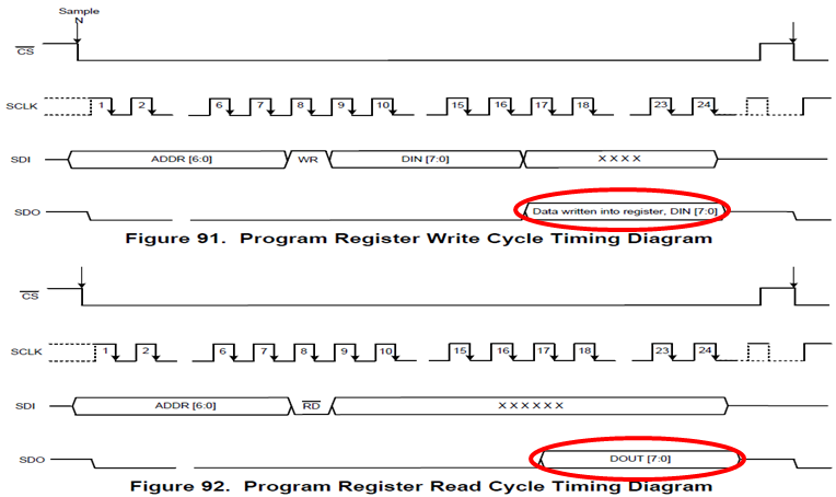
    You said when you send commands with the same pins under SPI, you can only get the buffer full of 1's. Can you please let me know if you are checking the data on SDO by writing or reading ADS8694's internal registers, or sending a command to select a channel for a data conversion? or for all of these commands, you got all 1's data back to MCU(8-bit data on the SDO for writing or reading registers highlighted as below screenshots, 16-bit data on the SDO for a conversion)?

    I noticed that your are using below SPI configuration in your SPI initialization code, actually ADS8694 will read the data on the SDI at every falling edge of the SCLK for capturing the command, also the MCU is expected to read the data on the SDO line at the falling edges of the SCLK, so the mode 1 (CPOL=0,CPHA=1) should be a correct configuration for SPI interface on MCU to communicate with the ADS8694 ADC. Please correct this and check again.

    SpiaRegs.SPICCR.bit.CLKPOLARITY = 0

    SpiaRegs.SPICTL.bit.CLK_PHASE = 0;

    If it still have the issue after modify the phase, I would like to check the timing plots for the digital pins under SPI configuration with an oscilloscope which is the best and simplest way to identify the issue.

    Thanks.

    Best regards

    Dale

  • Good morning Dale,

    many thanks again, I was changing the configuration to CPOL=0,CPHA=1 as you suggested. Die issue is still there.

    Answering your question, I get 1`s  for all of the commands I send. I check the data after I send 16 bits and check again after the whole package has being transmitted. SDO is always high. Or, better said: reading SPIRXBUF gives only 1`s

    I checked also not allowing pullup in the line, without changes in the reading.

    I even checked it by using other pins for spi, but nothing changes.

    So, in order not to waste your time, I suggest, I first go to my desk and check everything with the osci, make a plot and send it to you next week.

    One question: Do I need to clean any registers before I start a new frame? In my code I have reinitialized fifos (spi_fifo_init(); and subsecuently the whole spi) after sending a command. I suppose, this is too brutal and not necessary, but I forgot to comment it out in the file I sent to you.

    Best regards!

    Gustavo

  • Hi Gustavo,

    I'm not clear about "clean" any registers, but for any register configuration, you only need to do once after power up the ADC, for example, input range registers if the range is same. For debug purpose, the less code and features using, the simpler debug, so do not use FIFO if possible, also try to use default register value without programming them. Please let me know when you get scope plots for digital signals, thanks.

    Best regards

    Dale

  • Hi Dale,
    I got my check with the Logic Analyzer and discovered that I had no CLK working on pin 60. Also pin 58 and 59 were behaving strange.
    The reason was a wrong spi-pin configuration. My fault, as expected :)

    It was:

    // GpioCtrlRegs.GPBMUX2.bit.GPIO58 = 1; // Configure GPIO58 as SPISIMOA
    // GpioCtrlRegs.GPBMUX2.bit.GPIO59 = 1; // Configure GPIO59 as SPISOMIA
    // GpioCtrlRegs.GPBMUX2.bit.GPIO60 = 1; // Configure GPIO60 as SPICLKA

    but it should be:

    // Configure GPIO58 as SPISIMOA
    GpioCtrlRegs.GPBGMUX2.bit.GPIO58 = 3;
    GpioCtrlRegs.GPBMUX2.bit.GPIO58 = 3;

    // Configure GPIO59 as SPISOMIA
    GpioCtrlRegs.GPBGMUX2.bit.GPIO59 = 3;
    GpioCtrlRegs.GPBMUX2.bit.GPIO59 = 3;

    // Configure GPIO60 as SPICLKA
    GpioCtrlRegs.GPBGMUX2.bit.GPIO60 = 3;
    GpioCtrlRegs.GPBMUX2.bit.GPIO60 = 3;

    Now I have it!
    We can close this (happy ). Thank you very much for the help!
    Sincerely,
    Gustavo