This thread has been locked.

If you have a related question, please click the "Ask a related question" button in the top right corner. The newly created question will be automatically linked to this question.

ADS114S06: Schematic Review for ADS114S06 using for PT100

Part Number: ADS114S06

Hi Experts,

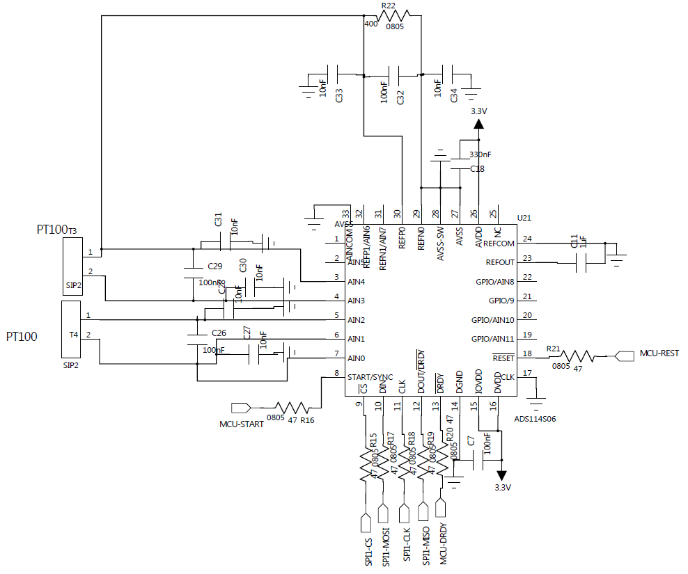
Our customer wants to use ADS114S06 to measure two PT100, can you help to review the schematic as below to see is there any issues? Thanks a lot!

  • Hi Jacky,

    I lack some specific details about configuration and operation. The schematic appears to be using two 2-wire RTDs. As one RTD is connected to the reference and the other to the current source, it appears that an external connection would be required to connect the RTDs together.

    If that is the intention, then there should be a connection shown between the RTD connectors. There is a potential problem with this method. If one of RTDs becomes open circuit then both measurements will have an issue. I would suggest connecting T3 and T4 connectors together at pin 1 and connect AIN5 to T3 pin 2 (or for easier routing change the input connections by sliding the inputs by one so that both RTDs are symmetrical in appearance to the T4 connections) using the additional analog input as a current source connection. This will make each measurement independent. You would then switch the current routing at the same time as the input mux is switched.

    I would also add input filter resistors between the connector and analog inputs. Make sure the IDAC current is connected to the RTD connector pin and not going through the filter resistors.

    It is not clear what amount of IDAC current will be used, but the reference voltage must be at least 0.5V. In the schematic the reference resistor is 400 Ohm. There are a couple of considerations. One the current through the reference resistor must be at least high enough to create a voltage of 0.5 V. Also, if PGA gain will be applied, the reference voltage must also be large enough to place the RTD input within the input range of the PGA. One other consideration is if the IDAC current is too large the current can cause self-heating of the RTD element.

    I would suggest reviewing the the application note SBAA275 and in particular the section on multiple 2-wire RTD measurements in section 2.9 starting on page 29.

    Best regards,
    Bob B
  • Hi Bob,
    Thanks for the comments.