


Part Number: ADS1248
Other Parts Discussed in Thread: ADS124S08, ADS1220, LM7705
Hello,
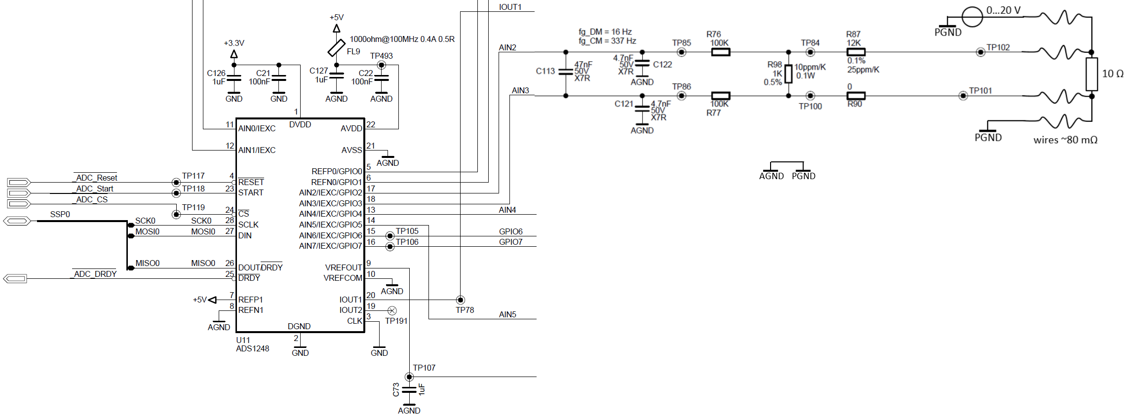
In my application I use an ADS1248 for remote voltage measurement on a power resistor.
AIN2 is connected to the positive rail of the resistor (Sense+).
AIN3 is connected to the negative rail of the resistor (PGND, Sense-).
My ADC is referenced to AGND, and AGND is connected to PGND on the same board.
ADC settings: Gain=1, use internal 2.048 V reference, input = AIN2-AIN3
Judging from the datasheet it seems that I violated the PGA Common-Mode Voltage Requirements as described in section 9.3.2.1. I would expect that the voltages are clipped at 100 mV at the ADC PGA's output.
Measuring between AIN3 and AGND I reach 100 mV only at Uresistor = 13 V.
Nevertheless, I my ADC counts look fine and they fit the ideal curve quite well.
Here is a plot of the voltage across the 10 Ohm resistor vs the measured ADC count, the ideal transfer function subtracted:

No offset or similar artifacts are visible.
In my understanding this is a mismatch between the theory and the measurements. Where is the gap? Am I just lucky or have I overseen anything?
Thanks for your comments,
Chris

