This thread has been locked.

If you have a related question, please click the "Ask a related question" button in the top right corner. The newly created question will be automatically linked to this question.

ADS1292R: lead-off dectection insensitive

Part Number: ADS1292R
Other Parts Discussed in Thread: ADS1292

Dear TI Experts,

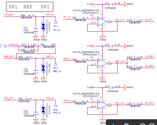
My customer is evaluating ADS1292R in a new project, they can hardly detect lead-off, could you kindly help to review below HW and SW and give some advice for this case? Thanks a lot.

FW initiation configuration:

    ADS1292_SendCommand(ADS1292_CMD_SDATAC);  

   ADS1292_WriteRegister(ADS1292_REG_CONFIG1, 0x01);  // continuous conversion mode,sample rate to 250sps

   ADS1292_WriteRegister(ADS1292_REG_CONFIG2, 0xe0);//Lead-off comparators enabled

   ADS1292_WriteRegister(ADS1292_REG_LOFF, 0xd0);//75% - 25%

     ADS1292_WriteRegister(ADS1292_REG_CH1SET, 0x60);//pga = 12

   ADS1292_WriteRegister(ADS1292_REG_CH2SET, 0x60);//pga = 12

   ADS1292_WriteRegister(ADS1292_REG_RLD_SENS, 0x2f);

     ADS1292_WriteRegister(ADS1292_REG_LOFF_SENS, 0x0F);  // Turn on both P- and N-side of all channels for lead-off sensing

   ADS1292_WriteRegister(ADS1292_REG_LOFF_STAT, 0x00);

   ADS1292_WriteRegister(ADS1292_REG_RESP1, 0x02);

   ADS1292_WriteRegister(ADS1292_REG_RESP2, 0x83);

   ADS1292_WriteRegister(ADS1292_REG_GPIO, 0x00);

   ADS1292_SendCommand(ADS1292_CMD_OFFSETCAL);

     nrf_delay_ms(200);

Key Register configuration

Reg

value

 01

 0x01

 02

0xe0

 03

 0xd0

 04

 0x60

 05

0x60

 06

0x2f

07

0x0f

08

0x00

09

0x02

0a

0x83


When INT comes, can hardly detect lead-off from the ADC data

 Channel data(24 status bits + 24 bits × 2 channels) = 72 bits   

 read 3 byte status register (1100 + LOFF_STAT[4:0] + GPIO[1:0] + 13 '0's) 

 LOFF_STAT[4:0] is RLD_STAT,IN2N_OFF,IN2P_OFF,IN1N_OFF,IN1P_OFF

  • Hi Bruce,

    Sure thing! We can take a look over the ADS1292R register details and schematic snips for you. In the meantime though, can you let us know what "hardly detect lead-off" means here? Is it slow to respond or does that mean that don't get the comparator function to work at all?
  • Dear Tom,
    Thanks for your help, in most cases, my customer don't get the lead-off function to work at all. Occasionally, it works.
  • Hi Bruce,

    Your electrode inputs appear to be AC-coupled. DC lead-off detection will not work.

    If the RLD output is being used to bias the subject, then you can replace the series capacitors with 0-ohm resistors on the ECG channels. You will need to keep Channel 1 AC-coupled if it is used for respiration measurements.


    Best Regards,

  • Dear Ryan,
    Thanks a lot for your support. Yes, at first time, the series capacitors caused DC Lead-off mode detaction failed. Follow your advice, customer tried to change to the AC Lead-off mode , however , it failed again, below are the result and the configration , could you kindly help to check again?

    LOFF_STAT[4:0] is RLD_STAT,IN2N_OFF,IN2P_OFF,IN1N_OFF,IN1P_OFF
    Reg value
    01 0x01
    02 0xe0
    03 0x11
    04 0x60
    05 0x60
    06 0x3f
    07 0x3f
    08 0x00
    09 0x02
    0a 0x83
  • Bruce,

    The comparators are used for DC lead-off detection only. AC lead-off is determined by post-processing the raw data and analyzing the magnitude of the signal at the lead-off current frequency.

    Please review the AC Lead-Off Section on page 53 of the data sheet.

    In addition, you may find the following application note helpful as well to learn the differences between the two methods:

    http://www.ti.com/lit/an/sbaa196a/sbaa196a.pdf

    There is also some useful training material about ECG applications on our training portal. The following video is part of a 6-part series detailing ECG applications and typical features.

    Best Regards,

  • Dear Ryan,
    Thanks for your support. It's very helpful.
  • Dear TI Experts,

            We change to the AC Lead-off mode,electrode 1 connected to REF_EXT,electrode 2 connected to FP2_EXT.Measure the channel 2,it was found that the success of the test was related to the contact time between electrode 1 and skin,Describe the following:

    1.At first,electrode 1 and electrode 2 maintain good contact with the skin.At this point,the LOFF_STAT[4:0] value is normal whether the electrode 1 or electrode 2 falls off,or both electrodes fall off simultaneously.

    Electrode 1 falls:LOFF_STAT[4:0]=01000;

    Electrode 2 falls:LOFF_STAT[4:0]=00100;

    Electrode 1 and electrode 2 fall off simultaneously:LOFF_STAT[4:0]=10000;

    2. But, if the contact time between electrode 1 and skin is longer than 15 seconds, AC Lead-off results will fail, and the LOFF_STAT [4:0] value will remain "10000". Unless the electrode 1 is kept away from the human skin for about 10 seconds at this time, and then the electrode 1 is re-maintained in good contact with the human body, it will return to the sucess state of detection. This abnormality is very regular, as long as the electrode 1 keeps in good contact with the body for more than 15 seconds, this will happen. But electrode 2 will not have this abnormal condition.

    Based on the above phenomenon,we want to know:

    1.If the comparator can only be used in DC Lead-off mode, why is LOFF_STAT [4:0] valid when we set it to AC Lead-off mode?

    2.In the AC Lead-off mode, although the value of LOFF_STAT[4:0] is detected effectively. But why does electrode 1 keep in good contact with the skin once more than 15 seconds will appear abnormal detection of this rule.

    Reg value
    01 0x01
    02 0xe0
    03 0x11
    04 0x60
    05 0x60
    06 0x3f
    07 0x3f
    08 0x00
    09 0x02
    0a 0x83

    Best Regards,