This thread has been locked.

If you have a related question, please click the "Ask a related question" button in the top right corner. The newly created question will be automatically linked to this question.

ADS122C04: Interfacing ADS122C04 (ADC 24 - Bit) with MSP430FR2633 using I2C on 8 MHz Clock SMCLK Clock

Part Number: ADS122C04
Other Parts Discussed in Thread: MSP430FR2633,

Hello All,

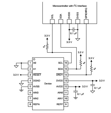
The Pin connection I did from below figure.
I'm using 10k resistor value as a pull-up and have a selected 100 kbps speed for I2C from the 8MHz SMCLK Clock.

I'm trying to interface ADS122C04 24-bit ADC with MSP430FR2633

I have written following algorithm:

1. Send Reset Command (0x06)

2. Write Configuration Register

a. Register 0 (0x40) = 0x81;

b. Register 1 (0x44) = 0x04;

c. Register 2 (0x48) = 0x00;

d. Register 3 (0x4C) = 0x00;

//Here I'm using Single short conversation mode and Single channel Read Mode

3. Send Start Command (0x08);

4.loop

{

Wait for DRDY Pin to transition low;

send Read Command (0x10);

}

The DRDY pin goes low after sending the start command.

The Above algorithm I have a implemented and I'm able to read only data = [0xFF, 0xFF, 0xFF] from ADC every time.
I'm also giving different voltage using potentio-meter on AIN0 Channel from 0 to 3.3v but I receive same data  (data = [0xFF, 0xFF, 0xFF]) on different voltages.

Here is my 8MHz Clock Configuration:
{
    __bis_SR_register(SCG0);                 // disable FLL
    CSCTL3 |= SELREF__REFOCLK;               // Set REFO as FLL reference source
    CSCTL0 = 0;                              // clear DCO and MOD registers
    CSCTL1 &= ~(DCORSEL_7);                  // Clear DCO frequency select bits first
    CSCTL1 |= DCORSEL_3;                     // Set DCO = 8MHz
    CSCTL2 = FLLD_0 + 243;                   // DCODIV = 8MHz
    __delay_cycles(3);
    __bic_SR_register(SCG0);                 // enable FLL
    while(CSCTL7 & (FLLUNLOCK0 | FLLUNLOCK1)); // Poll until FLL is locked

    CSCTL4 = SELMS__DCOCLKDIV | SELA__REFOCLK; // set default REFO(~32768Hz) as ACLK source, ACLK = 32768Hz
                                                     // default DCODIV as MCLK and SMCLK source
}

Here is my I2C Configuration:
{
    UCB0CTLW0 |= UCSWRST;                   // Put eUSCI_B in reset state
    UCB0CTLW0 |= UCMODE_3 | UCSSEL_3 | UCMST | UCSYNC; // I2C master mode, SMCLK
    UCB0BRW = 0x33;                          // Set Bit rate 100 kHz
    UCB0I2CSA = 0x40;                       // ADC122C04 slave Device address
    UCB0CTLW0 &= ~UCSWRST;                  // Software Reset Disable

}

Please do needful.

Regards,

Kelvin

  • Hi Kelvin,

    I would start simple as possible and use a scope or logic analyzer to verify your communication. If you have shots of the communication, please attach them so I can verify.

    Initially you send a RESET command. Make sure you wait long enough for the reset to complete before attempting to write the registers. Try reading back the registers after they are written to verify the register write was completed successfully.

    If DRDY goes low after the START command is issued, it would appear that part of the communication is working at least for single byte writes. If the registers were written properly, you should see DRDY toggling at the specified data rate (every 50ms). If you do not see DRDY toggling, then the registers were not written correctly and you may have issues with multi-byte writes (and reads). Make sure that you get an ACK for every byte transmitted from the micro. The register write sequence should follow similar to Figure 59 on page 39 of the ADS122C04 datasheet. If a stop is issued between bytes transmitted, then the command will cancel.

    Best regards,
    Bob B
  • Hi Kelvin,

    For me to be of any more help I will need to see scope or logic analyzer shots of your communication and the specific code you are using to write registers and read data.

    Best regards,
    Bob B
  • Hi Bob,

    Thanks for your prompt reply and valuable suggestions.
    Already, I have attempt all the suggestions of yours. Also, verify what I have a written to register and read back using Register Read command.
    It seems to good. There is no error in this iteration.

    My code is working by little change in I2C configuration.
    Here is my I2C Configuration:
    {
    UCB0CTLW0 |= UCSWRST; // Put eUSCI_B in reset state
    UCB0CTLW0 |= UCMODE_3 | UCSSEL_3 | UCMST | UCSYNC; // I2C master mode, SMCLK
    UCB0BRW = 0x8; // Set Bit rate 100 kHz
    UCB0I2CSA = 0x40; // ADC122C04 slave Device address
    UCB0CTLW0 &= ~UCSWRST; // Software Reset Disable

    }

    I have a change UCB0BRW register setting only.
    Chnaged UCB0BRW = 0x33 to UCB0BRW = 0x8

    After changing this setting I also getting accurate counts on ANI0 Channels.

    Regards,
    Kelvin Kalariya