This thread has been locked.

If you have a related question, please click the "Ask a related question" button in the top right corner. The newly created question will be automatically linked to this question.

DAC8742HEVM: configure to FOUNDATION Fieldbus/PROFIBUS PA mode

Part Number: DAC8742HEVM
Other Parts Discussed in Thread: PROFIBUS

Hi,

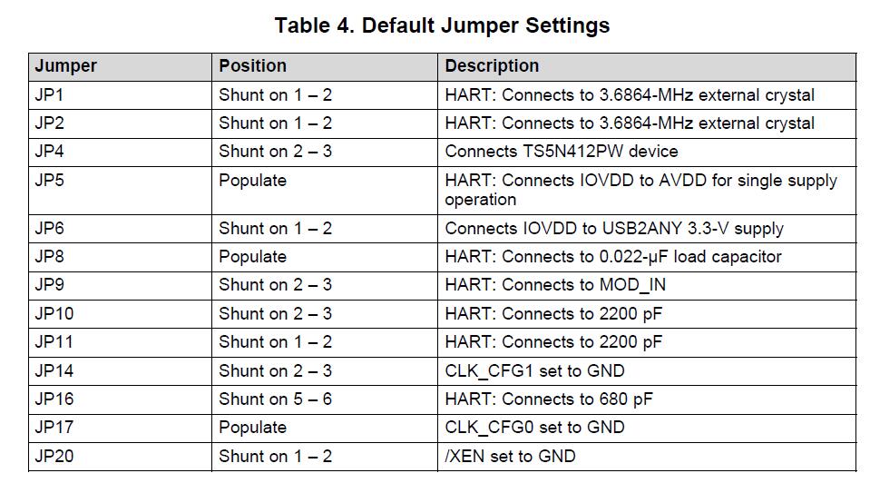
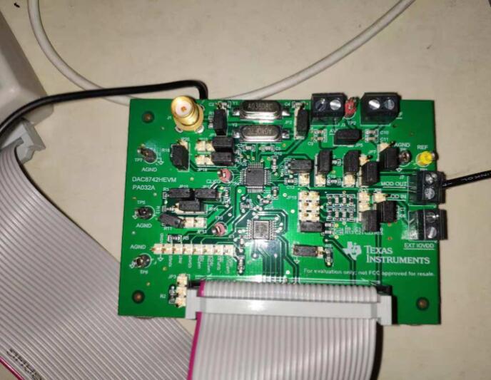
There are many jumpers in DAC8742HEVM. Could you pls provide a checklist about how to configure it to SPI Interfaced FOUNDATION FIELDBUS / PROFIBUS PA mode?

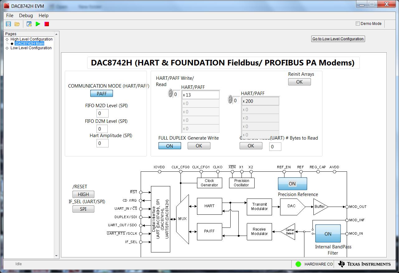
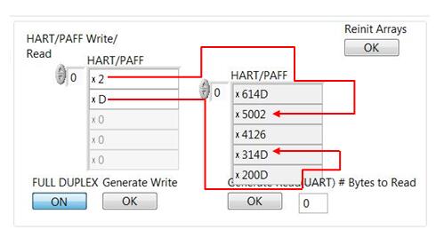
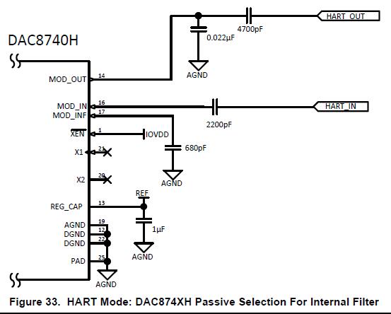
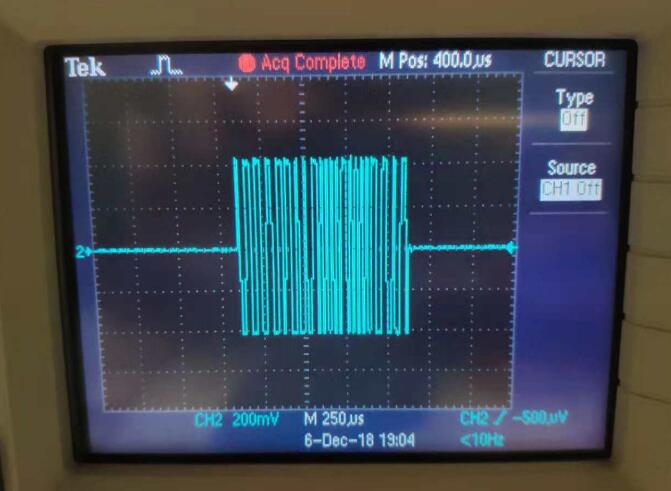
I tried to configure it by EVM User Guide, and generate data by Hart/PAFF Write in GUI. I measured signal on MOD_OUT with oscilloscope, but I'm not sure if it transmits the correct data. Could you show me a simple way to confirm it?

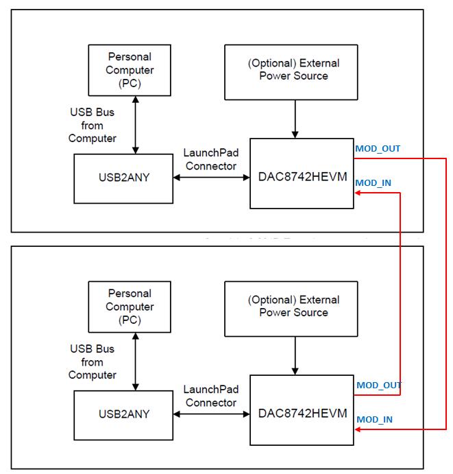
I would like to build a small network with two EVMs as below shows. Do you think it will work?

Thanks.

  • Hi Jerry,

    See below for the jumper configurations for PA/FF mode:

    JP1: (2-3), JP2: (2-3), JP3: open, JP4: (2-3)

    JP5: closed, JP6: (1-2), JP7: open, JP8: open

    JP9: (1-2), JP10: (1-2), JP11: (2-3), JP12: NC,

    JP13: open, JP14: (2-3), JP15: closed, JP16: (7-8)

    JP16: 7-8, JP17: closed, JP18: open, JP19: open, JP20: (1-2)

    In the EVM GUI enable the internal reference, internal BPF, and select PAFF mode. Then you should be able to load the write FIFO and click generate write to transmit. One way of checking is enabling FULL DUPLEX to read back the modulated waveform.

    Let me know if you run into any issues with this.

    Thanks,
    Garrett
  • Thank you, Garrett.

    I configured the jumpers according to your reply as blow shows. In GUI, I found whatever I generated write to transmit, the read back value was always x200. What does this value mean?

    I used a cable to connect MOD_OUT and MOD_IN on J7 to do loop-back configuration for read back. Do you think it might damage the MOD_IN port?

    How to configure the values in COMMUNICATION MODE?

    Thanks again.

  • Hi Jerry,

    The 0x200 indicates the end of the read. When data is received each byte from the FIFO will be listed followed by 0x200 when the RX fifo is empty.

    No, this is the intention of full-duplex and it will not damage MOD_IN.

    I don't think it is required to change anything under 'communication mode'. Are you seeing a waveform on MOD_OUT?

    Thank,
    Garrett
  • Hi Garrett,

    I made some little changes JP13(1-2: SPI mode), JP9(2-3: MOD_IN), below shows my configuration. I used a cable to connect MOD_OUT to MOD_IN on J7 for loopback. Now, I saw the waveform on MOD_OUT. After enable FULL DUPLEX, I can read back the data. As below shows, I can find where the '2' and 'D' I wrote into PAFF Write in PAFF Read, even if I don't know the meaning of x614D/x4126/x314D.

    Is the passive selection of PAFF MOD_OUT/IN  the same to Figure 33 in datasheet for HART?

    Thanks again.

  • Hi Jerry,

    You are correct, JP9 should be connected in 2-3 configuration. JP13 can be floating as it is controlled by the EVM software to select between SPI/UART.

    Your scope capture and data read back look okay. The sent bytes are on lines 2 and 5 at FIFO levels 5 and 2. The first nibble indicates the FIFO level (0-15). The other bytes you are receiving in the FIFO are preamble bytes and stop bytes per the FF/PA protocol (0x0126, 0x014D). This is described in section 8.4.4 of the datasheet.

    The main passive change will be for filtering. If using the internal filter in PAFF mode a 120pF capacitor should be connected to MOD_INF. Also a lower capacitance 0-100pF is required for stability.

    Let me know if you have additional questions.

    Thanks,
    Garrett