This thread has been locked.

If you have a related question, please click the "Ask a related question" button in the top right corner. The newly created question will be automatically linked to this question.

ADS122C04EVM: ADS122C04EVM With External Microcontroller

Part Number: ADS122C04EVM
Other Parts Discussed in Thread: ADS122C04

Hello,

I am trying to prototype with this EVM and a STM32F446RET6 Microcontroller. I believe I have configured the EVM correctly to communicate with another MCU, but I cannot seem to get an ACK from the ADC on any I2C Address, while other devices do respond so I think my problem pertains to my modifications on the EVM.

I have removed the following components and Jumpers:

  • Removed R57  and R60, Jumped Address Lines both to VDD (3V3), address should be $45. Other devices on $20 and $10
  • Cut the Net-Ties on RST, SCL, SDA And nDRDY going to the TIVA MCU
  • Populated JP2 and JP1
  • Powering the ADS122C04 via Jumper wires from Host MCU Board to 3V3 and GND pins on J3

What additional modifications must I make to allow proper communication to my Host?

Kind Regards,

Luke

  • Hi Luke,

    Welcome to the E2E forum!  I would suspect that either the RESET pin is not being held high, or AVDD is not properly connected to a voltage source.  The ADS122C04 will be held in a reset state until RESET is held high and all supplies are at a nominal operating voltage (both AVDD and DVDD at the pins of the ADS122C04 must be supplied).  By default jumper JP11 is connected to 5V which is supplied by the USB on the EVM.  Make sure that AVDD at JP11 is set to 3.3V (DVDD) position.

    Also make sure you are pulling the RESET pin high (DVDD) on the ADS122C04.

    Best regards,

    Bob B

  • Bob,

    Thank you for the reply. I have confirmed that RESET is tied to 3V3 and AVDD is 3V3 on all nets surrounding the ADS122C04. Is there any other configuration?

    Best,

  • Hi Luke,

    There shouldn't be any other additional requirement. Send my some scope or logic analyzer shots of your communication for me to verify.

    Best regards,
    Bob B
  • Bob,

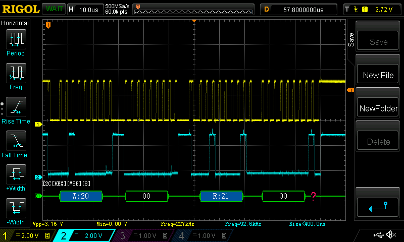
    Here is an I2C transaction with a valid device on the bus:

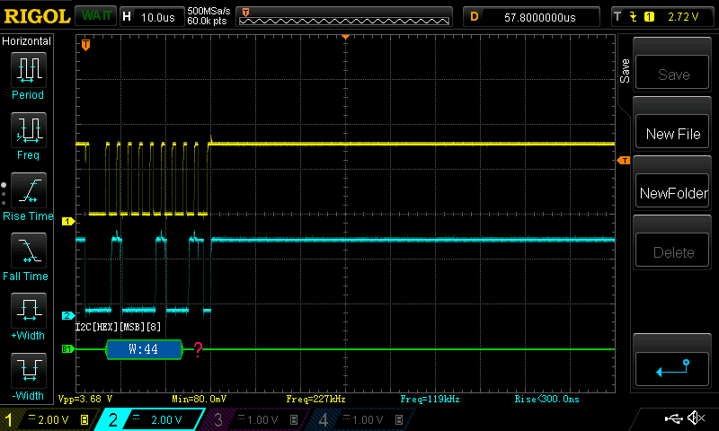
    Here is at the address programmed for the ADS122C04 (A0 = A1 = DVDD):

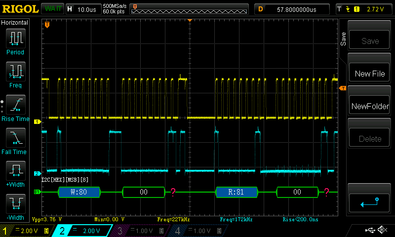
    And here is where the device seems to attempt to respond at a totally different address not listed in the datasheet:

    You can see the absence of ACKS

  • Hi Luke,

    Thanks for the scope shots. In the datasheet for the ADS122C04 there is Table 14 on page 35. This shows that for both address inputs connected to DVDD the I2C address is 100 0101 (0x45). Your scope shot is showing something different in two ways. The first is the address is implemented incorrectly and second it would appear you are using 100 0100 (0x44).

    The implementation for I2C addressing of the device is not writing 0x45 to the device. The actual addressing for I2C with the ADS122C04 is 7-bit address shifted left 1 followed by the R/W bit. The correct format when transmitted would appear as 1000 1010 ( 0x8A) for a write or 1000 1011 (0x8B) for a read.

    In your last screen shot you are actually transmitting an address of 100 0000 (0x40), which is a valid address where A1 and A0 are both at DGND.

    Best regards,
    Bob B
  • Thank you Bob, I can see that now. However why would the device ack an address that is different from the configuration? A1 and A0 are measured at 3.28V (DVDD).
  • Hi Luke,

    I've been making an assumption, which is probably not a good one. How are you pulling the address pins high? Have you measured the voltage at the device pins?

    You removed R57 and R60 which would float the inputs. To pull these address pins high you would need to install a pullup resistor at R55 and R58. If you installed headers at JP7 and JP8, you would need to instead install shorting resistors (or place a short) across R56 and R57 to connect the JP7 and JP8 to the address pins.

    Best regards,
    Bob B
  • Hello Bob,

    Yes, I had removed R57 and R6, then placed the jumpers to pull the A0 and A1 lines to DVDD.

    Thank You for your help so far!
  • Hi Luke,

    What do you mean by jumpers and where did you place the jumpers? Did you measure the voltage at the device pins of the ADS122C04 for verification?

    Best regards,
    Bob B
  • Bob,

    I am terribly sorry to have wasted your time, I should have checked my work more closely! It turns out when I removed R57 and R60 I did not populate R59 and R56. I had not measured at the IC Pins, only the Jumper! I have now confirmed that the address lines. This has fixed the problem.

    Kine Regards,
  • Hi Luke,

    Glad you got things to work. I'm here to help and glad that in some small way was able to help guide your through to finding the issue. Feel free to start a new post if you have any further issues or questions.

    Best regards,
    Bob B