Other Parts Discussed in Thread: ADS7842
Hello all,
I am working with the BOOSTXL-ADS7841-Q1 through TM4C1294's SPI interface.
I am having a problem of getting the ADC to generate output data. I checked the timing requirement and I am sure I've match everything with the datasheet.
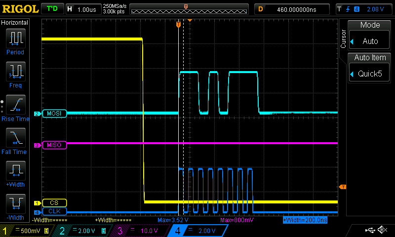
Please take a look at my scope snippet along with the code I am using to generate the output.
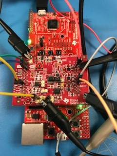
Here is my setup
The Vref I am using is 4.5 V
The MISO line and the BUSY line always stay low no matter what I do
Here is the timing requirement charts for your convenience
And here is my code - I initialize the spi interface and then put the function ads7842_read_data() into an infinite loop to debug with the scope.
The CONTROL BYTE I am sending is
[1][1][0][1][0][1][1][1] = 0xD7
void init_ads7842(uint32_t sysClock) {
    uint8_t flush_buffer[10];

    /* Enable Pins for SSI usage */
    SysCtlPeripheralEnable(SYSCTL_PERIPH_GPIOQ);
    SysCtlPeripheralEnable(SYSCTL_PERIPH_GPIOM);
    SysCtlPeripheralEnable(SYSCTL_PERIPH_GPIOP);

    /* Enable SPI interface */
    SysCtlPeripheralEnable(SYSCTL_PERIPH_SSI3);

    GPIOPinTypeGPIOInput(GPIO_PORTQ_BASE, GPIO_PIN_3);  // MISO - configure it as GPIO input
    GPIOPinTypeGPIOOutput(GPIO_PORTQ_BASE, GPIO_PIN_2); // MOSI - configure it as GPIO output
    GPIOPinTypeGPIOOutput(GPIO_PORTQ_BASE, GPIO_PIN_0); // SCLK - configure it as GPIO output
    GPIOPinTypeGPIOOutput(GPIO_PORTM_BASE, GPIO_PIN_7); // ~CS - configure it as GPIO output
    GPIOPinTypeGPIOInput(GPIO_PORTP_BASE, GPIO_PIN_3);  // BUSY - configure it as GPIO input

    /* Set Chip Select To Logic High */
    ads7842_chip_select(UNSELECT);

    /* Configure Clock, MISO and MOSI in for SSI3 */
    GPIOPinConfigure(GPIO_PQ0_SSI3CLK);
    GPIOPinConfigure(GPIO_PQ2_SSI3XDAT0);
    GPIOPinConfigure(GPIO_PQ3_SSI3XDAT1);


    /* Configure the GPIO settings for the SSI pins. This function
        also gives control of these pin to the SSI hardware.*/
    GPIOPinTypeSSI(GPIO_PORTQ_BASE, GPIO_PIN_0);
    GPIOPinTypeSSI(GPIO_PORTQ_BASE, GPIO_PIN_2);
    GPIOPinTypeSSI(GPIO_PORTQ_BASE, GPIO_PIN_3);

    /* Disable SS3 to Configure it */
    SSIDisable(SSI3_BASE);

    /* Configure setting for SPI interface with the speed of 8MHz - it takes 1us to send 8 bits */
    SSIConfigSetExpClk(SSI3_BASE, sysClock, SSI_FRF_MOTO_MODE_1, SSI_MODE_MASTER, 2500000, 8);

    /*
     SSI_ADV_MODE_LEGACY      0x00000000
     SSI_ADV_MODE_READ_WRITE    0x000001c0
     SSI_ADV_MODE_WRITE         0x000000c0
     SSI_ADV_MODE_BI_READ       0x00000140
     SSI_ADV_MODE_BI_WRITE      0x00000040
     SSI_ADV_MODE_QUAD_READ     0x00000180
     SSI_ADV_MODE_QUAD_WRITE    0x00000080
    */

    SSIAdvModeSet(SSI3_BASE, SSI_ADV_MODE_LEGACY);

    /* Enable SSI3 */
    SSIEnable(SSI3_BASE);

    /* Flush remaning data in FIFO */
    while(SSIDataGetNonBlocking(SSI3_BASE, (uint32_t*)&flush_buffer[0]))
    {
    }


}

void ads7842_read_data() {

    uint32_t buffer[16];
    ads7842_chip_select(SELECT);

    SSIDataPut(SSI3_BASE, 0xD7);
    ads7842_check_busy();
    Delay(500);
    SSIDataGet(SSI3_BASE, buffer);

    ads7842_chip_select(UNSELECT);
    Delay(100);

}

void ads7842_chip_select(CHIP_SELECT option) {
    if (option == SELECT) {
        GPIOPinWrite(GPIO_PORTM_BASE, GPIO_PIN_7, 0);
        set_board_led(BOARD_LED_2, LED_ON);
    } else if (option == UNSELECT) {
        GPIOPinWrite(GPIO_PORTM_BASE, GPIO_PIN_7, GPIO_PIN_7);
        set_board_led(BOARD_LED_2, LED_OFF);
    }
}

void ads7842_check_busy() {
    if(GPIOPinRead(GPIO_PORTP_BASE, GPIO_PIN_3) == GPIO_PIN_3) {
        set_board_led(BOARD_LED_1, LED_ON);
    } else {
        set_board_led(BOARD_LED_1, LED_OFF);
    }
}
Please advise me of what approach I can take to solve the issue.
Thanks,
Alex


