This thread has been locked.

If you have a related question, please click the "Ask a related question" button in the top right corner. The newly created question will be automatically linked to this question.

BOOSTXL-ADS7841-Q1: Does the ADS7841-Q1 Evaluation Board mean to work only with EEPROM?

Part Number: BOOSTXL-ADS7841-Q1
Other Parts Discussed in Thread: ADS7841-Q1, ADS7841

Hello,

I am having a hard time to get the BOOSTXL-ADS7841-Q1 to work with the TM4C1294 LaunchPad. The behavior is as follow.

If I use the GUI program, I am able to get the data and everything as expected. However, if I program my own application to interface with the IC through SPI, no matter what I do, it doesn't seem to work. 


Please advises me on the situation, should I buy a standalone IC and work with it rather than using the BOOSTXL-ADS7841-Q1?

Thanks,

Alex

  • Hi Hua,

    The EEPROM is only there to identify the ADS7841-Q1 Booster Pack to our software GUI. There is no reason to worry about it while running your own code.

    I see you got some advice on this query from the 'TM4C' guys as well. Ralph's suggestion to change the phase of your SPI transfer to "mode 0" is good, MISO and MOSI should be strobed on the rising clock edge. You need to transfer 24 bits in total, the MASTER device controls the SCLK. In the first 8-bits you transmit the control word and the MSB (Start bit) MUST be a set to get a conversion started. The next two bytes you have to transmit 0x00 to generate the necessary SCLKs to process the conversion routine and read out the data.

    Just curious, but in your initial post, I did not see where you accounted for the /SHDN pin, can you verify that pin 7 on the ADS7841-Q1 is not being driven/held low?
  • Tom,

    You make my gloomy and snowy weekend a lot better!

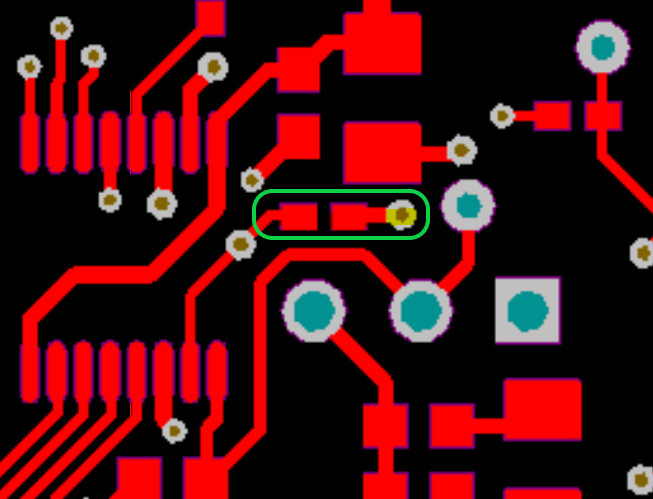
    I checked the /SHDN pin and it was held low... The datasheet stated that it was always pulled high by VDD (See picture below), that is why I didn't question the integrity of the pin.

    I check the resistor R21 that was connected to the pin and the side it is connected to VDD has 5V while the side it is connected to /SHDN is 0V. 


    What would be the cause of this? Since it is still working with the GUI program...

    Thanks,
    Alex

  • Tom,

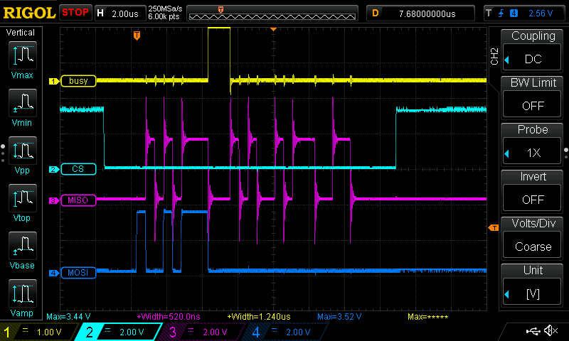
    So I manually put 3.3V into the /SHDN pin and it works (based on visual inspection on oscilloscope)

    So now is the question of how can this happen?


    Thank you so much! You are brilliant,

    Alex

  • Hi Alex,

    Happy to hear that it's working now! I suppose it really depends on how you connected the EVM with your processor. Pin 7 of the ADS7841 also connects to U5 pin 3, which comes through via pin U5 pin 6. If the SHDN_TIVA signal was left to float ahead of the level shifter, you can't guarantee a state on its output. The ringing on your MISO is really bad BTW - I hope that is just a probe grounding issue. Please do feel free to let us know if there is anything else we can help with.
  • Tom,

    I now see that the ~SHDN was exposed as well. Thank you very much for your help!

    Have a wonderful week ahead,
    Alex