This thread has been locked.

If you have a related question, please click the "Ask a related question" button in the top right corner. The newly created question will be automatically linked to this question.

ADS122U04EVM: Possible to communicate via COM-Port

Part Number: ADS122U04EVM
Other Parts Discussed in Thread: ADS122U04, MSP-EXP432E401Y, MSP430FR5994

Hi together,

I'm pretty new to the ADS122u04EVM. Have made some Data-Collections via Delta-Sigma ADC Evaluation Software. This functions very well.

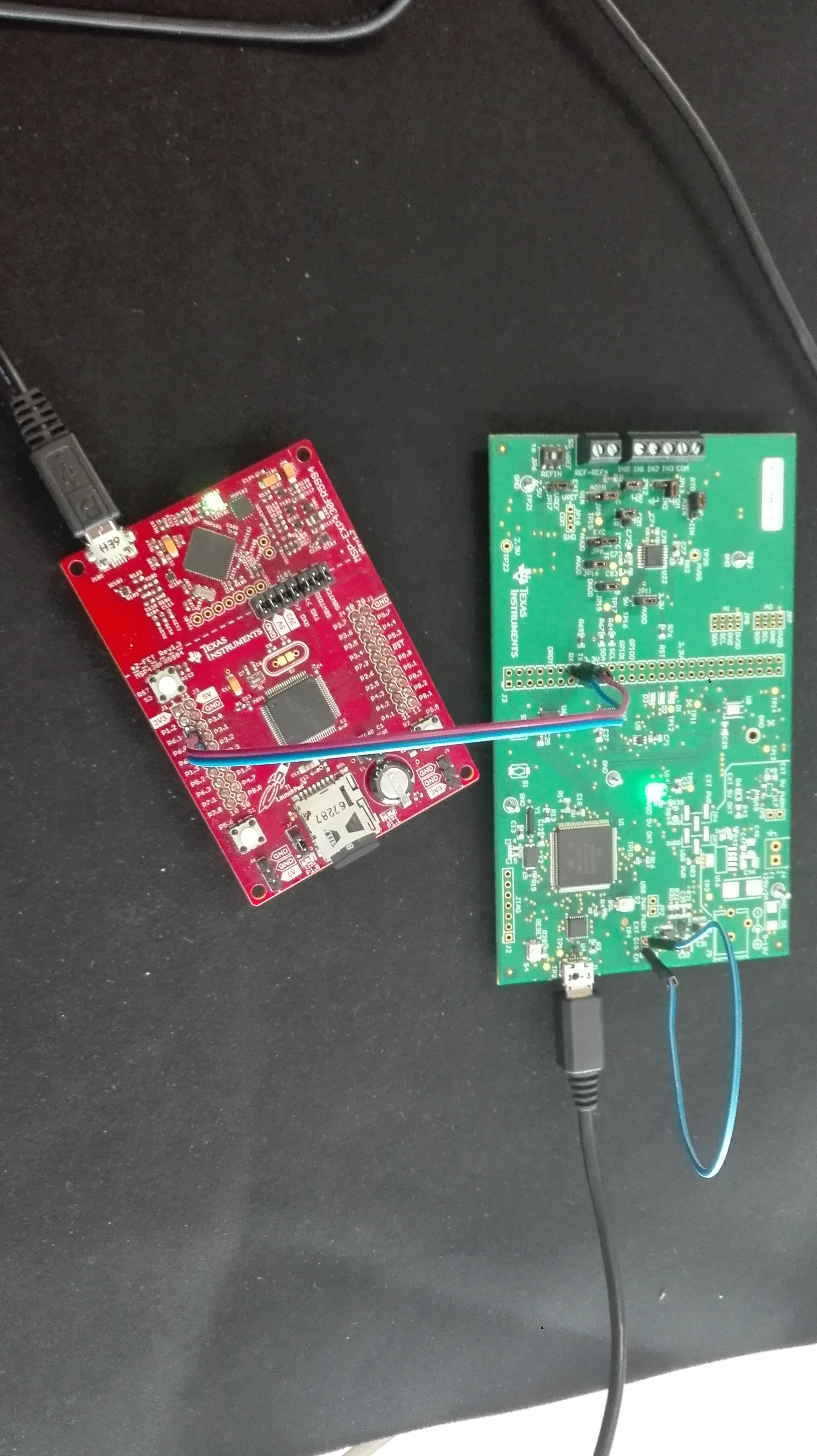
Now i want to try to get a Conversations to the ADS122u04 via Serial Port, is that possible with the ADS122u04EVM? For example, i want to send the commands with an vba-module, and then collect the data. The problem i see is that i haven't a Virtual Com Port in the Device Manager for that purpose only the Generic Bulk Device. I hope somebody can help me with this question.

Sorry for the bad english.

Friendly Greets, Jan

  • Hi Jan,

    Welcome to the E2E forum!  The ADS122U04 on the ADS122U04EVM communicates to the onboard Tiva microprocessor.  The Tiva uses a USB Bulk enumeration to communicate to the GUI.  So the Tiva is a bridge between the ADS122U04 and the PC.  There is no virtual COM connection using the USB, nor is there a direct way to communicate to a PC from the ADS122U04 device itself.  There have been a few people that have attempted this, but you would need a special USB to UART cable or interface to connect the two together.  You would also need to disconnect the communication to the Tiva and connect to the other communication method.  In other words, you would need to create your own bridge for communication and the bridge must use the proper voltage levels for the ADS122U04.  You cannot use RS232 levels.

    The second issue is when using a standard COM terminal it is difficult to send and receive data as many of the communication commands are not printable characters.

    If you send me your end goals, I may be able to help you get started.  One method I can think of is to get a TI LaunchPad that includes a USB port that can be programmed to operate as a USB serial port.  One that I often use is the MSP-EXP432E401Y which contains a debugger port that also includes a back channel UART (virtual COM port) that can be used for communication.  The LaunchPad also has a micro that can be used as a bridge and a PC connection can be made using the back channel UART.  On line tools are available for building a GUI (GUI Composer) and for writing code (Code Composer Studio) to communicate to the ADS122U04.  See below:

    https://dev.ti.com/

    Best regards,

    Bob B

  • Thanks for the helpful answer Bob,

    my endgoal is to use an excelsheet to collect and show the data results. The Registers should be set by an included table. The enddata should be printed an additional table. For that purpose i want to use an makro that uses the win-api to get a communcation to the serial port. Thats an example for 20SPS, so i use a sleep time of 50ms in the continous-conversation between each data i would receive.

    Here is a short summary what the makro-module does:

    - getting data of the excel table: settings for each register (saving in a value of 1 Byte for each), getting the number of samples to receive,

    -initialize the communication to the serial port (port id, baudrate, paritiy, number of databits, stopbit)

    -sending snychro and resetcommand (&h55,&h06) then sleep 50ms

    -loop for 0 to 4: sending synchro an registersettings commands with &h55, &h40,&h03 for example, next iteration: &h55,&h41,&h02 and so on (the register setting are only for example like in the first &h03)

    -setting ads122u04 in continous-conversation-mode by sending &h55, &h08

    -now loop with the number of samples that should be collected:

    -checking DRDY in register 3 to control if new data is available by sending &h55, &h22

    -if data isn't available try again uo to 10 times

    -if data available send &h55, &h10

    -receive data and put it into a variables (3Bytes)

    -sleep 50ms

    -print data in to a cell in the table

    -next iteration, up to the iteration number that is the same as the sample number to collect

    shutting down the ads122u04 with &h55, &h02 ; then closing the serial connection

    If i understand you right, then that should be possible by using for example an usb to serial adapter that includes an TTL-Uart (for example with an ft232bl). Then i have to remove the connection on the ads122u04evm that lets the tiva microchip and the ads122u04 communicate. So it should now be possible to connect the RX,TX pins from the adapter to the TX,RX marks on the EVM? In theory would it work this way?

    Thanks a lot, greets Jan

  • Hi Jan,

    The easiest thing to do is to use the USB power as the power source to the EVM.  If you install or solder a jumper on the EVM at JP1 (just above the USB connector on the EVM) this will disable the level shifters on the EVM and hold the Tiva micro in a reset state.  You can then safely connect to the TX and RX labeled pins on the J3 connector (long 50 pin connector near the center of the board).  Using this method allows the power for AVDD to be selectable at either 5V or 3.3V and the digital to be 3.3V.  In the end you must make sure whatever bridge you use output the signals at 3.3V and not RS232 levels.

    One such device is the FTDI board TTL-232R-3V3-PCB.  This board plugs into a USB port and can be cabled to the TX and RX pins as the output levels are operating at TTL logic levels.  I've seen other similar boards available from other manufacturers.

    Best regards,

    Bob B

  • Hi Bob,

    sorry for the late reply, was ver busy the last time, but thanks for your intention to help me.

    I've found a msp430fr5994evm in my collection, so i've tried to use it for a extern communication as an uart. As you explained I installed a jumper to set the Tiva chip into reset state. Then I connected the uart-pins of the msp430fr5994evm to the j3 pins on the ads122u04evm (rx to tx, tx to rx). For the msp430fr5994 i use a programm in which i've defined two uarts. The code is posted below. UCA0 is used as a software uart, so i use a terminal program connected to the port4 to transmitt data to the msp430fr5994. this data is transmitted to the second uart, which is used as the connection between the msp430fr5994evm and the ads122u04evm.

    But sadly thats doesn't solve my probelm, i doesn't get any data transfered by the ads122u04. Perhaps you can help me again.

    Thanks and greets Jan Dombrowski

    #include <msp430.h>
    unsigned char data1;
    
    int main(void)
    {
        WDTCTL = WDTPW | WDTHOLD;               // Stop Watchdog
    
    
        // Configure GPIO
        P6SEL1 &= ~(BIT0 | BIT1);
        P6SEL0 |= (BIT0 | BIT1);                // USCI_A3 UART operation
    
        P2SEL0 &= ~(BIT0 | BIT1);               //usci0
        P2SEL1 |= BIT0 | BIT1;
    
        // Disable the GPIO power-on default high-impedance mode to activate
        // previously configured port settings
        PM5CTL0 &= ~LOCKLPM5;
    
        // Startup clock system with max DCO setting ~8MHz
        CSCTL0_H = CSKEY_H;                     // Unlock CS registers
        CSCTL1 = DCOFSEL_3 | DCORSEL;           // Set DCO to 8MHz
        CSCTL2 = SELA__VLOCLK | SELS__DCOCLK | SELM__DCOCLK;
        CSCTL3 = DIVA__1 | DIVS__1 | DIVM__1;   // Set all dividers
        CSCTL0_H = 0;                           // Lock CS registers
    
        // Configure USCI_A3 for UART mode
        UCA3CTLW0 = UCSWRST;                    // Put eUSCI in reset
        UCA0CTLW0 = UCSWRST;
        UCA3CTLW0 |= UCSSEL__SMCLK;             // CLK = SMCLK
        UCA0CTLW0 |= UCSSEL__SMCLK;
    
        // Baud Rate calculation
        // 8000000/(16*9600) = 52.083
        // Fractional portion = 0.083
        // User's Guide Table 21-4: UCBRSx = 0x04
        // UCBRFx = int ( (52.083-52)*16) = 1
        UCA3BRW = 52;     // 8000000/16/9600
        UCA0BRW = 52;
        UCA3MCTLW |= UCOS16 | UCBRF_1 | 0x4900;
        UCA0MCTLW |= UCOS16 | UCBRF_1 | 0x4900;
        UCA3CTLW0 &= ~UCSWRST;                  // Initialize eUSCI
        UCA0CTLW0 &= ~UCSWRST;
        UCA3IE |= UCRXIE;                       // Enable USCI_A3 RX interrupt
        UCA0IE |= UCRXIE;
    
        __bis_SR_register(LPM3_bits | GIE);     // Enter LPM3, interrupts enabled
        __no_operation();                       // For debugger
    }
    
    #if defined(__TI_COMPILER_VERSION__) || defined(__IAR_SYSTEMS_ICC__)
    #pragma vector=EUSCI_A3_VECTOR
    __interrupt void USCI_A3_ISR(void)
    #elif defined(__GNUC__)
    void __attribute__ ((interrupt(EUSCI_A3_VECTOR))) USCI_A3_ISR (void)
    #else
    #error Compiler not supported!
    #endif
    {
        switch(__even_in_range(UCA3IV, USCI_UART_UCTXCPTIFG))
        {
            case USCI_NONE: break;
            case USCI_UART_UCRXIFG:
                while(!(UCA3IFG&UCTXIFG));
                UCA0TXBUF = UCA3RXBUF;
                __no_operation();
                break;
            case USCI_UART_UCTXIFG: break;
            case USCI_UART_UCSTTIFG: break;
            case USCI_UART_UCTXCPTIFG: break;
            default: break;
        }
    }
    
    #if defined(__TI_COMPILER_VERSION__) || defined(__IAR_SYSTEMS_ICC__)
    #pragma vector=EUSCI_A0_VECTOR
    __interrupt void USCI_A0_ISR(void)
    #elif defined(__GNUC__)
    void __attribute__ ((interrupt(EUSCI_A0_VECTOR))) USCI_A0_ISR (void)
    #else
    #error Compiler not supported!
    #endif
    {
        switch(__even_in_range(UCA0IV, USCI_UART_UCTXCPTIFG))
        {
            case USCI_NONE: break;
            case USCI_UART_UCRXIFG:
                while(!(UCA0IFG&UCTXIFG));
                UCA3TXBUF = UCA0RXBUF;
                __no_operation();
                break;
            case USCI_UART_UCTXIFG: break;
            case USCI_UART_UCSTTIFG: break;
            case USCI_UART_UCTXCPTIFG: break;
            default: break;
        }
    }
    

  • Hi Jan,

    From your code it looks as if you have set up 2 UARTs, but with the intention of passing data between the UARTs. I don't see any way of handling or transferring data to/from the ADS122U04. What data are you sending to the ADS122U04? If you connect a scope on the RX and TX lines, do you see a transfer of communication?

    Best regards,
    Bob B
  • hey bob,
    i finally managed to get a conversation startet. Actually i'm i little confused cause i didn't thought it would work this way.
    First to get you the information, yes the posted code enables the use of 2 uarts and yes they are transfering data to each other. One of them is an software uart that is transmitting the data from the pc via the usb connection, its shown as com port in the device manager of windows named "msp application uart". The second uart ist the one of the msp430fr5994evm on the pins 6.0 and 6.1. This Pins im using to connect them to the TX and RX on the ADS122U04EVM. The msp430 uses the interrupts to check if data is received from the pc, if so its putting it on the tx-buffer from the second uart. Now the information is transmitted to the ads122u04-rx-port. If i#m receiving an answer from the ads122u04, the second interrupt activates to get the received data moved to tx-buffer from the first uart, that is now transitting the data to the pc.
    Whats confusing me is the fact that i disconnected the jumper und j1, that you suggested me to install to put the tiva in reset state. Now its working the way as i wish it to be, but the j1 ist now disabled. If im installing the jumper again, i doesn't receive any data.
    If you have an idea what is up there please tell me.
    But in the end my problem is solved, thanks a lot and friendly greets.
  • Hi Jan,

    How are you powering your board(s)? If JP1 is open, then the Tiva processor is connected to the ADS122U04. You actually could be communicating with the Tiva processor instead of the ADS122U04. It is possible that the level shifters are causing a problem by loading the TX/RX signals.

    You could also try cutting the two traces between the left-hand and right-hand side of the J3 connector where it is labeled TX and RX. If you cut these traces (seen on top-side of the board) then the Tiva and level shifters are no longer in circuit.

    Another potential reason why you might think the ADS122U04 is working may be due to when the Tiva is running, the RESET pin (labeled RST on the J3 connector) is being pulled high. You must make sure this pin is high or the device will be in a reset state.

    Best regards,
    Bob B
  • Hi Bob,
    thanks for reply. For testing purpose i'm using the power supply by usb-port for both boards. The whole commands are working the way it intended to be, with jp1 disconnected. If im installing the jumper, i didn't get any communication, so i think as you suggested that i'm communicating with the tiva instead.
    I will check for your hints later.

    Thanks and Greets Jan
  • Hi Jan,

    Maybe you could also take a picture of your setup and how things are connected for me to see.

    Thanks,
    Bob B
  • Hey Bob,

    i've taken a pciture of the situation the usb-cables are connected to my pc. Ifi try to get an conversation in this state, i receive no answer from ads. If i remove the jumpercable at jp1, it is working.

  • Hi Jan,

    When JP1 is connected there is no longer a voltage present to pull the RESET pin high.  This will hold the ADS122U04 in a reset condition.  I suggest adding a pull-up resistor (10k to 100k) to the J3 connector,  You would solder one end of the resistor to the point marked RST and the other end of the resistor to the point marked 3.3V.  I would also suggest that you connect the LaunchPad ground and the EVM grounds together.  This should get you going.

    Best regards,

    Bob B

  • Thanks a lot bob now it's working i totally didn't realized about the Reset-Pin
    Greets Jan