This thread has been locked.

If you have a related question, please click the "Ask a related question" button in the top right corner. The newly created question will be automatically linked to this question.

ADS8668: EXTERNAL CV INPUTS with ADS8668

Part Number: ADS8668
Other Parts Discussed in Thread: TIDA-01214, ADS8688, DAC7571

Hi

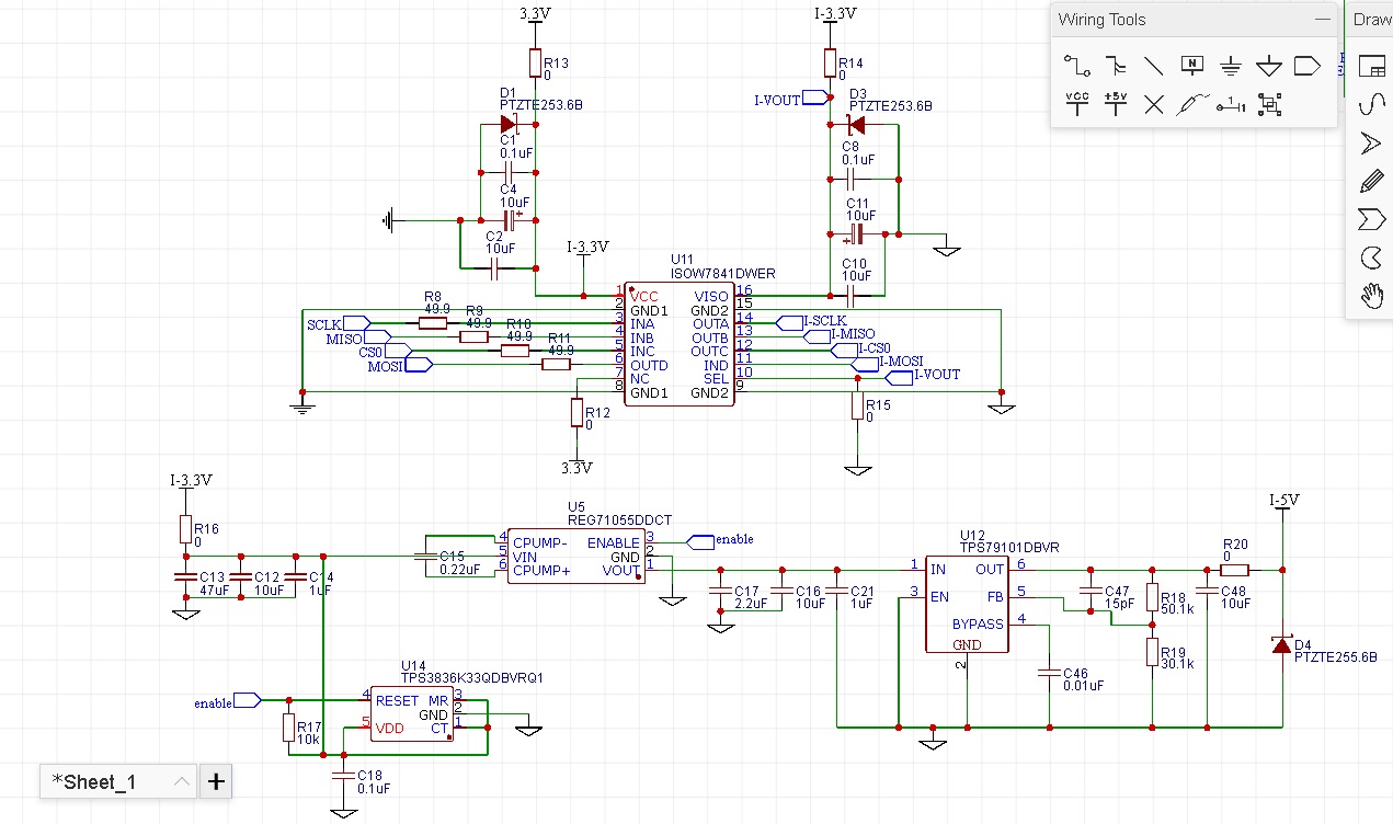
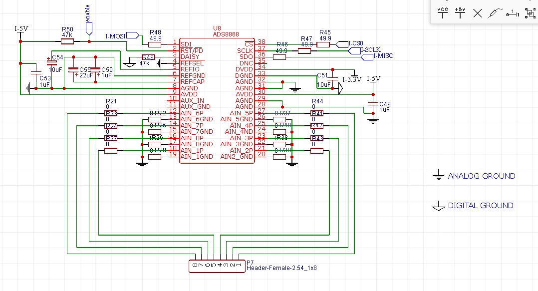
I would like to ask if the setup in the picture could be taken into account for the setup of ads8668 controlled by a teensy 3.6

Kind regards

  • Hello Pierluigi,

    As I recommended to you in previous post, the reference design TIDA-01214 on TI.com is the exactly right design for you, this is a isolated data acquisition system using ADS8688/ADS8668. Please refer to the schematic as below: 

    http://www.ti.com/general/docs/lit/getliterature.tsp?baseLiteratureNumber=tidrsj3&fileType=zip

    check the web link in my previous post for more information including layout or design user guide.

    Thanks&regards

    Dale

  •  Hi Dale!

    Thanks for linking the documents, please have a look if i got this bit right

  •  i link the wiring of ads8668, please tell me if you see anything wrong

  • Hi Pierluigi,

    For your ADC schematic, 

    • A balanced RC filter on each input channel can help to filter noise, please refer to ADS8688EVM schematic in user guide on TI.com.
    • DAISY pin can be connected to ground directly or with a 0ohm resistor.
    • AUX_IN and AUX_GND can be connected to ground since you will not use this channel.
    • You are using split ground(Analog and Digital), they should be connect at one point. If you do not have this experience, a solid entire ground is strongly recommended, see layout guideline in datasheet.
    • ADC's name should be ADS8668, not ADS8868.

    For power, I'm not expert for those devices, please refer to the reference design which was shared to you.

    Thanks&regards

    Dale.

  • A balanced RC filter on each input channel can help to filter noise, please refer to ADS8688EVM schematic in user guide on TI.com.

    Please, have a look at the picture i attach below. Is this right? If so what value you suggest for resistors?

    You are using split ground(Analog and Digital), they should be connect at one point. If you do not have this experience, a solid entire ground is strongly recommended


    Yes, i don't have that experience, such as this one !!.. :-D But, i really need your help on this point.

    I've connected grounds as seen on one of the designs mentioned and i've been reading about star grounds, maybe this would be the case to use it?

    Well, i'm quite scared of noises also because all signals come from a bigger board which connects to the external panel, all analog signals there. 

    The ADCs board shares GND with the bigger board.  On the ADC board are also allocated teensy, a dac7571, and 4 cd74hc muxs. 

    I know splitting grounds and designing pcb for that is a big hassle, but i want to understand how worthed could be.

    Considering, i'm only wondering, i think it was better to give you these details to evaluate the path to take on GND design.

    Thanks again Dale, you're my angel.

    P.S. Is the reset chip necessary in my design?

  • Hi Pierluigi,
    For RC filter, R28,R71 and C29 filter is a correct balanced input filter, the RC value will determine the bandwidth of filter, the large value can have a low bandwidth to filter more noise but large R may lead to gain error and drift can be an issue, please refer to the app note on our website:
    www.ti.com/.../sbaa239a.pdf
    www.ti.com/.../sbaa319.pdf
    You will have to decide these component values regarding your system requirement.
    For the ground, a clean ground is required to achieve the performance specified in ADS8688's datasheet,otherwise, you wmay get the worse performance than the specifications in datasheet. Also, the voltage on AIN_xGND should be in the range -0.3~0.3V, it may cause latch-up issue and damage the device. These limits and information have been described in ADS8688's datasheet (layout guideline and maximum input ratings). These are guideline for the layout including ground.
    Your current schematic about /RESET is good. After power up the ADC, a reset signal can guarantee to reset the ADC to default status.

    Thanks.

    Regards,
    Dale

  • Hi Dale

    Thanks for the links.

    Considering the inputs frequencies won't exceed 64 Hz i guess the 10k res with 24nF cap could be a good option (320 Hz cut)., let me know if you thumb up.

    On Grounds.

    In current design all inputs are phisically on another board and all inputs grounds go on that board ground.

    Shall i consider bringing the single input grounds singularly to the ADC board for best operation? 

    Also, considering the two boards are going to share grounds , is there a way to "clean" the first board ground, before getting to the ADC board?

    Thanks a lot again Dale,

    Regards 

  • Hi Pierluigi,

    ADS8668 has an integrated AFE and ADC driver and the front-end circuit design is not critical to drive the ADC like other switch-capacitor input ADCs, so this RC you plan to use is fine for this ADC, the only concern may be system gain error and drift because 10kohm is not small if comparing with 1Mohm input impedance on ADS8668. You can adjust the RC value when you test on the hardware board regarding the performance required by your system.

    For the ground connection, I suggest to have a local ground connection on AIN_xGND with a balanced input resistor. A solid analog ground plane is recommended regarding the layout guideline in datasheet. Also, definitely you should have a ground connection between ADC board and the first board. I'm not sure what kind of connector or cable you will use for the signals and ground connection between these two boards, but a short connection and coaxial shielded cable should help on interference immunity.

    I hope these are helpful for you. Thanks.

    Best regards

    Dale

  • "For the ground connection, I suggest to have a local ground connection on AIN_xGND with a balanced input resistor"

    By using the "local" word you mean on the board where phisically input are or you mean on the adc board?

    Above i did put the RC on the inputs board, H1_2 is going to ADC board, if that is correct i could connect ADCs ground pins straight to ADC board ground?

    Thanks for your patience

    Regards

    Pier

  • Hi Pier,
    Local ground means that the ground plane on ADC board. It is better to place the balanced input RC filter on ADC board and close to the ADC, please check ADS86xxEVM user's guide.
    For this front-end amplifier circuit, I'm not sure if there is a special reason you used R7/U39, I did a simulation regarding to your circuit, the result was same. You may have a query on amplifier's E2E forum if have a special reason. Thanks.

    Best regards,
    Dale
  • Hi Dale, the part of the circuit you're mentioning is an attenuverter, just imported from a ready circuit. It is supposed to do this:

    at knob value 0 it multiplies incoming signal by -1
    at knob value 0.5 it multiplies incoming signal by 0
    at knob value 1 it multiplies incoming signal by 1

    Kind regards
  • Hi Pier,
    Thanks to let me know. Please let me know if you have further question about ADS8668.

    Best regards,
    Dale
  • Hi Dale, please have a look at the pcb design, hope is not bad

  • Hi Pier,

    I cannot review a layout in this way, if you do not want to show the pcb layout in public, please share the entire layout file to me after request friendship. Thanks.

    Regards,

    Dale

  • ok thanks, sorry, can we remove it? i will upload to you the whole board
  • Hi Pier,
    Okay, I will close this thread. Thanks.
    Regards,
    Dale