This thread has been locked.

If you have a related question, please click the "Ask a related question" button in the top right corner. The newly created question will be automatically linked to this question.

DAC8871EVM: EVM overheating and receiving no output from DAC

Part Number: DAC8871EVM
Other Parts Discussed in Thread: DAC8871,

Me and my senior design team are having trouble getting the DAC8871 and DAC8871EVM to function. When using the DAC8871, we are not getting an output when sending data which we would expect ~7V. We are concerned that we have some issues in our code as we are using the SPI library with an Arduino Mega 2560. When using the EVM and applying recommended power to Vcc & Vss, U5 seems to overheat and we are unable to test the module at all. 

Any help is appreciated as we're coming to the end of the semester and have not resolved this issue.

Thanks.

  • Hi Skyler,

    Can you share your exact jumper configuration that you are using on the EVM? Maybe also the supplies you are using and where they are connected?

    Thanks,
    paul
  • Hi Paul,

    Thanks for the response. The jumpers are all in the default jumper configuration, i.e., configured for the on board +/-10V reference.

    Skyler

  • Hi Skyler,

    In the past we have noticed that R14 is populated on the board, when it should be DNI. You should remove that resistor. You should also confirm that all the power rails are being provided (VCC, VSS, and VDD). Measure the reference values on TP1 and TP2 to confirm if the values seem correct (+10V, -10V). Finally, I would use a scope or logic analyzer to confirm that your SPI is formatted correctly.

    Thanks,
    Paul
  • Paul,

    When VCC and VSS are in the required range (+/-13.5V to +/-19.8V) and VDD ~5V, the reference voltage is about 200mV. If I apply just below required operating voltage, the reference voltage reads just under +/-10V and U5 does not overheat. Then when increasing supply voltage above the minimum operating voltage, Vrefh & Vrefl jump back down to 200mV and U5 overheats.

    I am removing R14 and will let you know of any changes.

    Thanks for your reply,
    Skyler
  • Paul,

    I removed R14 and this resolved the overheating and reference voltage issue, I am now seeing correct voltage references. Now my second issue is that I am receiving no output from the DAC when sending code 0000h as well as FFFFh over SPI, which should result in a -10V to 10V output. Any ideas? Would you like me to post my code to this forum?

    Thanks,
    Skyler
  • Hi Skyler,

    Good to hear about R14 solving the overheat problem - the amplifier and INA were probably fighting each other! We are updating the DAC8871 evm currently to simplify the reference design.

    In regards to the SPI communication - I think an oscilloscope is the easiest way to confirm that your SPI formatting is correct, and the data is being set up and latch on the correct edge. Most commonly on MCU's I find that the user has the wrong polarity and phase for the clock line. These modes are usually configurable when you initialize the SPI interface. You could try playing with those. It should not take too long, there are only four modes.

    Thanks,
    Paul
  •  Paul,

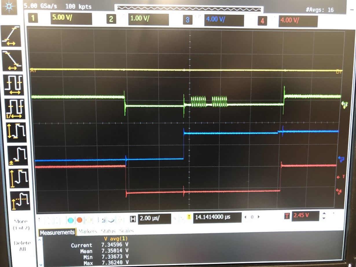
    I've messed around with the clock modes, I'm almost sure this DAC uses SPI_MODE_0. But I still cannot get an output other than Vrefh. I define CS, LDAC, SDI, and SCLK as outputs then write CS to low, LDAC to high, and transfer data. The latch and clock polarity seem to be correct but again, I only get a 10V output. I attached the scope readings and code being used. Yellow - Vout, green - SCLK, blue - LDAC, red - CS.

    #include <SPI.h>
    
    const int CS = 53;            //pin53 chip select
    const int SCLK = 52;         //pin 52 clock
    const int SDI = 51;         //pin 51 MOSI serial data
    const int LDAC = 43;       //pin 43 LDAC 
    
    const int V_refh = 10;       //high reference voltage
    const int V_refl = -10;     //low reference voltage
    byte output_0, output_1;
    
    
    void setup() {
    Serial.begin(115200);
    pinMode(CS,OUTPUT);
    pinMode(LDAC,OUTPUT);
    digitalWrite(CS, HIGH);
    pinMode(SDI,OUTPUT);
    pinMode(SCLK,OUTPUT);
    SPI.begin();
    }
    
                            
    //byte mydata_1 = 0b00000000;                          
    //byte mydata_2 = 0b00000000;
    //byte First_byte = mydata >> 8;                 
    //byte Second_byte = (mydata  << 8) & 0xFF;     
    
    void loop() {
        SPI.beginTransaction (SPISettings (50000000, MSBFIRST, SPI_MODE0));
        digitalWrite(CS,LOW);
        digitalWrite(LDAC,HIGH); 
        SPI.transfer(0b10000000);
        SPI.transfer(0b00000000);
        digitalWrite(CS,HIGH);
        digitalWrite(LDAC,LOW);   
        //Serial.println(First_byte, BIN);
        //Serial.println(Second_byte, BIN);
        SPI.endTransaction();
    }
    

    Thanks,

    Skyler

  • Hi Skyler,

    1. I do you think you are using the LDAC pin as described in the timing diagram. LDAC should be pulsed low while CS is high, but for now, just keep LDAC low all the time. That will allow the DAC to update as soon as the SPI command is complete.

    2. Your data line is very low. The scope is setup for 1V/division and it looks like the SDI is only at 500mV. What is the cause of this? Do you require a pullup on that pin from the MCU?

    Thanks,
    Paul