This thread has been locked.

If you have a related question, please click the "Ask a related question" button in the top right corner. The newly created question will be automatically linked to this question.

ADS8598H: Interfacing an ADC with a Microcontroller

Part Number: ADS8598H
Other Parts Discussed in Thread: REF3440, ADS8588H, TMS320F28377D, REF3425

Hello,

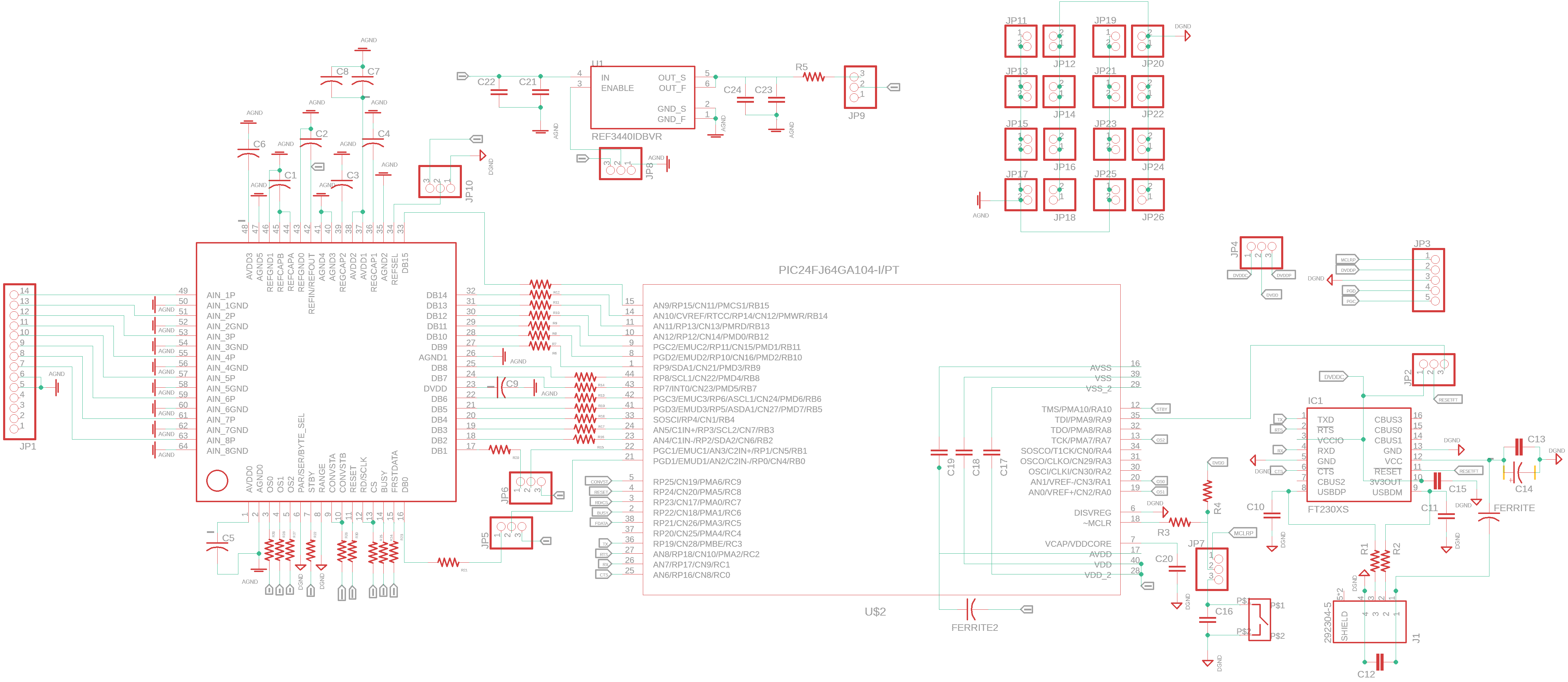
I am making my custom board which include the ADS8598H and a the PIC24FJ64GA104. I want to make a straight connection between the digital pins of the ADC and the MCU but in some forums, I have seemed people talking about External memory interface... and now I am starting to doubt: Is it possible to connect the ADC and the MCU directly ? . I would also appreciate a fast check to my schematic since is my first time using the ADS8598H. (I have seen other people using PIC before but I need to double check)

Thank you.

  • Hi Mateo,

    I do not know what External Memory Interface other guys talked about, but definitely ADS8598H can be connected to MCU directly with proper interface. I will check this schematic and get back to you soon.

    Thanks&regards

    Dale

  • Thanks Dale Li 

    your comment is a relief. 

  • Hi Mateo,

    It is hard to check your schematic, for example, there is no symbol for CONVSTA/B pins, but there is a symbol with "CONVST" on your MCU's pin 5. I guess you have a connection between ADC's CONVSTA/B and MCU's pin 5, but I do not know where you connected them. same things for RESET and many other pin and signals. Some observations about this schematic:

    1. ADS8598H requires 2.5V external vreference voltage, but REF3440 in your schematic is a 4.096V voltage reference.

    2. Suggest to have pull-up or down resistors on some important pins, for example, pull-down RESET with a resistor and capacitor, pull-up BUSY signal with a resistor, pull-up /STBY with a resistor, JP10-3 for REFSEL is pulled up with a registor..See ADS8588SEVM for more details.

    2. There is no value on capacitors, for example, C1 should be 10uF, C2 should be 10uF, please refer to the datasheet for requirements.

    3. I'm not sure if you are connect AVDD and DVDD pins to one same power supply because they are using a same symbol "-".

    4. It is good to have a balanced RC filter on each analog input, refer to ADS8588SEVM for more details.

    5. Jumper connection for analog and digital ground may not a good solution, I guess you are trying to find the best location for ground connection through tests and different jumpers, a surface mount footprint is better than jumper. You can connect pin 6(Par.SER/Byte), pin 8(Range) and JP10-1 pin to the solid analog ground (AGND).

    Refer to ADS8588SEVM User Guide for more details.. Also, there is another thread on E2E about the connection ADS8588H and MCU(TMS320F28377D), for your reference.

    http://e2e.ti.com/support/data-converters/f/73/p/725867/2678778?tisearch=e2e-quicksearch&keymatch=mcu#2678778

    Thanks&regards

    Dale

  • Hi Dale Li,

    Thank you very much for your response it was really helpful for us. Sorry for the schematic I didn't realize that some of the labels were not possible to see.

    Regarding the advice:

    1) We change the ref circuit for the REF3425.

    2) We add some pull-up resistors: STBY, REFSEL, RESET, OS2 and OS1 (the reason behind OS1 and OS2 is that we mainly want 64 OS ratio). We didn't add any pull-up resistor in the Busy terminal (out pin) could you explain to us why is it necessary? Even when we decided to follow the pull-up resistor advice, are they really necessary when we are using push-pull PIC output?.

    3) We didn't put values in the schematic sorry for that, the capacitor in REFCAP and REFI/O are 10uF and the other is 1uF.

    4) We didn't put the balance RC filter mainly because we don't have 0.0.1% resistors and the acquisition system includes anti-aliasing filters and low out impedance.

    5) Finally, we decided to remove all the Pin-Headers and make a solid ground plane as recommended in the Datasheet.

    6) what is the output type and input type for the ADC pins? 

    Please let me know what do you think about these considerations.

    Thank you very much.

  • Hi Mateo,
    2) BUSY is a important signal if you monitor it to read the data, the pull-up is optional, it will be better to have it in case there is any interference signal to lead to a wrong indicator on BUSY.
    6) I'm not sure which pin you asked about. If you really care about it, I will have to check with design team and it will take some time.
    Thanks.
    Regards,
    Dale