This thread has been locked.

If you have a related question, please click the "Ask a related question" button in the top right corner. The newly created question will be automatically linked to this question.

AMC1303E2520: Random false measurements

Part Number: AMC1303E2520
Other Parts Discussed in Thread: TMS320F28379S, AMC1303M2520, AMC1306M05, AMC1306E05, TMS320F28377D

Hello,

I have the same problem as MarkoAnte and Fearghal Kineavy (see these four topics: https://e2e.ti.com/support/data-converters/f/73/p/791462/2927525 , https://e2e.ti.com/support/microcontrollers/c2000/f/171/t/791077 , https://e2e.ti.com/support/data-converters/f/73/t/717467 , https://e2e.ti.com/support/microcontrollers/c2000/f/171/t/716608 )

I use six AMC1303E2520 with a TMS320F28379S to measure isolated voltages. Some of them work well and others give me random false measurements. I checked the supply voltages and the transmitted data (everything is clean), try to change the chips, the MCU and so on.

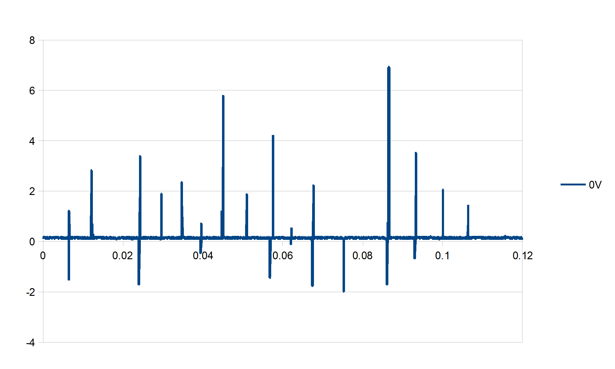
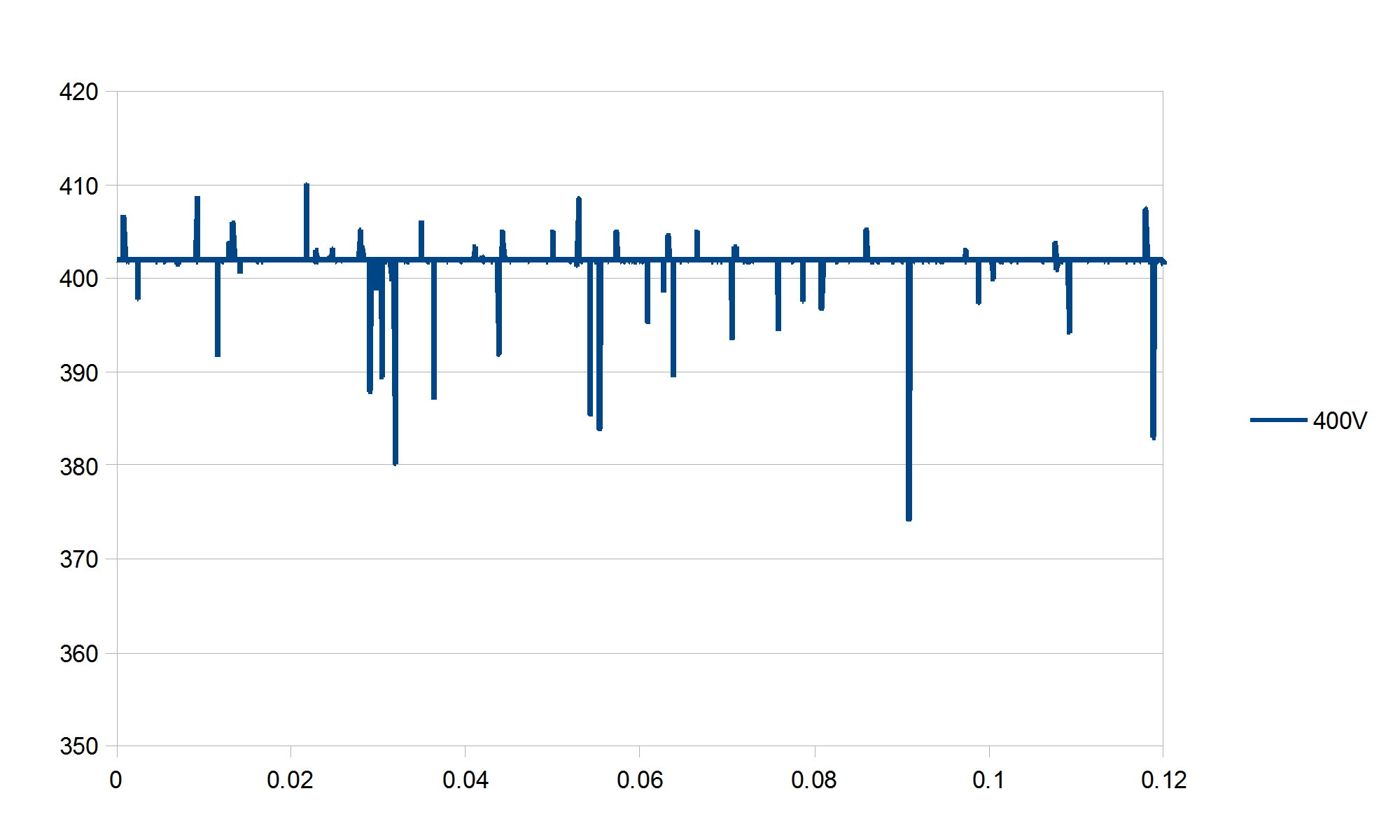
The only thing that evolves is the density and amplitude of the spikes in my measurements with each replacement AMC1303, until one of them agrees to work correctly. The erroneous results compared to legit ones vary from about one over 200 to about one over ten, depending on the chip. The amplitude of the spikes varies from about one to ten percent of full scale. On a single board, I have unsoldered-resoldered like fifteen chips to have a working system. This is a pretty expensive way to work.

The measured input voltages are always kept in the +/- 250mV range. The power supply is 5V on HV side, 3.3V on LV side, both clean and stable. There is a 100R resistor on each Manchester line just at the AMC1303 output. I used the same schematic as Figure 55 in the AMC1303 datasheet, including the R3’ resistor. I use Sync3 filter and 256 oversampling. SYSCLK runs at 200MHz.

Finally, thanks to MarkoAnte and Fearghal Kineavy, I replaced one of the particularly stubborn AMC1303E2520 with an AMC1303M2520, connecting the clock as best as possible with a wire. I only changed the SDFM mode and the GPIO for clock input, and it works perfectly. Unfortunately, I cannot do the same for all six of them, as the corresponding clock inputs on the TMS320 are already in use for other essential functions. With the remaining budget and time for the project, I cannot afford to redesign a new board using AMC1303M.

Is there anything I can do other than playing AMC1303 roulette? I am currently testing a second board identical to the first one, and the problem is exactly the same.

Thank you, best regards

Marc-André

  • Hi Marsouin,

    I'm sorry to hear you are having trouble with the Manchester operation of the AMC1303E2520 and the SDFM of the TMS320F28379S. Let me take some time to chat with the C2000 team and see if we can come up with a solution for you. In the meantime, can you provide any screen captures of the Manchester bit stream as it comes into the SDFM module (i.e. - at the TMS320F28379S side of the track)?
  • Marc,

    Questions based on your query:-

    1. What GPIO input qualification are you using on SDFM pins?
    2. Are you using SDSYNC option? If you are using, did see the problem even after disabling SDSYNC option
    3. Is there random noise coupling on SD-modulated signal?
    4. I would also try to reduce the input voltage well below 250mv to see whether you see the same behavior as mentioned in

    Regards,

    Manoj

  • Hello Tom, Manoj,

    Unfortunately, I already unsoldered yesterday all the non-working AMC1303 and I am waiting for fresh ones. They should arrive at the beginning of next week. Not the best idea I realize now, sorry. Therefore, I cannot measure anything for the moment. I will keep you informed as soon as I have news.

    Manoj,

    1. I use asynchronous input
    2. I don’t use SDSYNC
    3. I don’t think so. I did not see anything while measuring the signal. I will check again when the new AMC1303 are in place.
    4. It doesn’t change anything, on two of them even 0mV gives rubbish. I added two measurements, one with 0V (short-circuit on the voltage divider) and 400V (equals 200mV on the input) to illustrate. However, I also noticed that one of the working AMC1303 goes crazy if the input exceeds +/- 250mV, even if it is bellow +/-320mV. It doesn’t matter though, there is a good margin in normal working condition.

    Thank you for your help, best regards

    Marc-André

  • Question for TI Apps engineers: Both pairs of threads mentioned above were marked as resolved, but ended up with the customers using the non-manchester encoded versions of the AMC1303 or AMC1306 and stating that they believed the SDFM module in the 2837x DSP was malfunctioning. The TI employees asked multiple questions and basically concurred that the engineers had done a good job eliminating other possible causes, but there was no resolution that fixed the manchester encoding.

    Is this a systemic problem? I'm working on a design now with AMC1306E05 and TMS320F28377D, and these three threads have me concerned that I'll end up having to use the AMC1306M05 version instead. However, I can't use the un-encoded variant, because I didn't route the clock signals to the SDFM inputs on the DSP, because I expected that the Manchester version would work properly.

  • Hi Andrew,

    Sorry for the delay here. I am not aware of any systemic issues with the SDFM of the TMS320F28377D using Manchester encoded devices. The issues I have seen usually stem from the quality of the clock and/or data received at the Cx and/or Dx inputs to the SFDM. In the case of a Manchester encoded modulator, it would be just the data line - excessive ringing can cause data integrity issues, which is the main reason I asked Marsouin (Marc-Andre) if he could provide screen shots for us. Lets see what he comes back with and go from there.
  • Hi Tom,

    Thanks for the reply. Is the non-coded version more robust to signal quality then? Because the two referenced threads (MarkoAnte and Fearghal Kineavy) both had success once they switched to non-coded, even with a soldered air-wire in at least one case.

    Thanks,

    Andrew

  • Hello,

    So, the new AMC1303E2520 finally arrived yesterday afternoon. I soldered them and voilà, no more problem, they work perfectly. Therefore, I cannot provide you a measurement of a faulty chip. I feel bad that I did not anticipate that.

    I noticed something though. On the new board, there were four chips marked with 79TG4 CKVP lot. Three of them did not work. The remaining two are from 74TG4 AVNG lot and are OK. The new chips Mouser just send me are also AVNG and as I mentioned above, they work well. On the first board, all the AMC1303E currently in place are AVNG. I search into my electronic waste bin, and all the unsoldered AMC1303 I found are CKVP.

    Before designing these PCB, I made a small proto board plugged onto a LAUNCHXL-F28377S to test the AMC1303E2520 in the way I needed them. All four chips on this proto are AVNG and they work well. Otherwise, I would not have use them on the main system.

    Conclusion, on sixteen working chips, one is CKVP (and I will recheck it twice), fourteen are AVNG and one is a non-Manchester version (that I will maybe “depatch” and re-replace by an AVNG). All other previously mounted CKVP were glitchy. Are you sure that there is no problem with this CKVP lot?

    Thank you, best regards

    Marc-André

  • Hi Andrew,

    There shouldn't be any difference from the modulator (the AMC1303 or AMC1306) standpoint. 

  • Hi Marc-Andre!

    Thank you for the update!  Let me look through our QC database and see if there have been any concerns about the 79TG4 CKVP device lot.

  • Tom,

    I suppose I meant robustness of the decoder in the DSP? Is the clock + data more robust to noise or signal quality than the manchester encoded version which has to extract the data and recover the clock?

    Thanks,

    Andrew

  • Hi Andrew,

    Not that I am aware of.  The SDFM decoder needs to have a clock running at least 8x the speed of the bit-stream to properly decode the data and since its generated internally on the DSP, I would like to believe it's going to be cleaner than a clock coming across the PCB from the modulator.

  • Hello Tom,

    Tom Hendrick said:
    Let me look through our QC database and see if there have been any concerns about the 79TG4 CKVP device lot.

    Thank you very much. I will be on vacation next week, but I am looking forward to hearing from you when I will be back to work.

    Best regards

    Marc-André

  • Hi Marc-Andre,

    I hope you enjoy your holiday!  Our QC engineers have checked, and there have been no quality issues reported with either lot trace codes you provided.

  • Hi Marc-Andre,

    I am from the C2000 team. Can you try the following experiments on your system when using Manchester mode.

    The signal of the AMC1303 to the TMS320 device goes through a GPIO mux before going to the SD filters in the chip.

    In the GPIO Mux you have the ability to:

    1. invert the input signal

    2. turn on/off synchronizer circuit (synchronized at 200MHz)

    3. Add some digital filtering (3 samples, 6 samples) after synchronization

    Not sure how your GPIO Mux inputs are configured, but if you take an input that is misbehaving and play around with the above mode settings and seeing if you obtain a more stable operation.

    Cheers,

    Alexander Tessarolo

  • Hi Tom,

    Tom Hendrick said:

    Our QC engineers have checked, and there have been no quality issues reported with either lot trace codes you provided.

    Thank you for the feedback. I guess I had no luck, then.

    Hello Alexander,

    Thank you for your message. The configuration on the SDFM pins is as follows:

    That being said, I will not touch anything now that my system seems so work.

    Best regards

    Marc-André