This thread has been locked.

If you have a related question, please click the "Ask a related question" button in the top right corner. The newly created question will be automatically linked to this question.

AMC1303M2510: Fail-safe output issue

Part Number: AMC1303M2510

Hi  Experts:

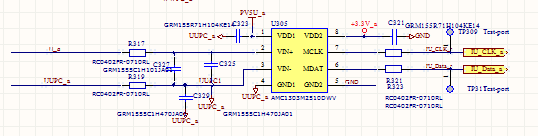
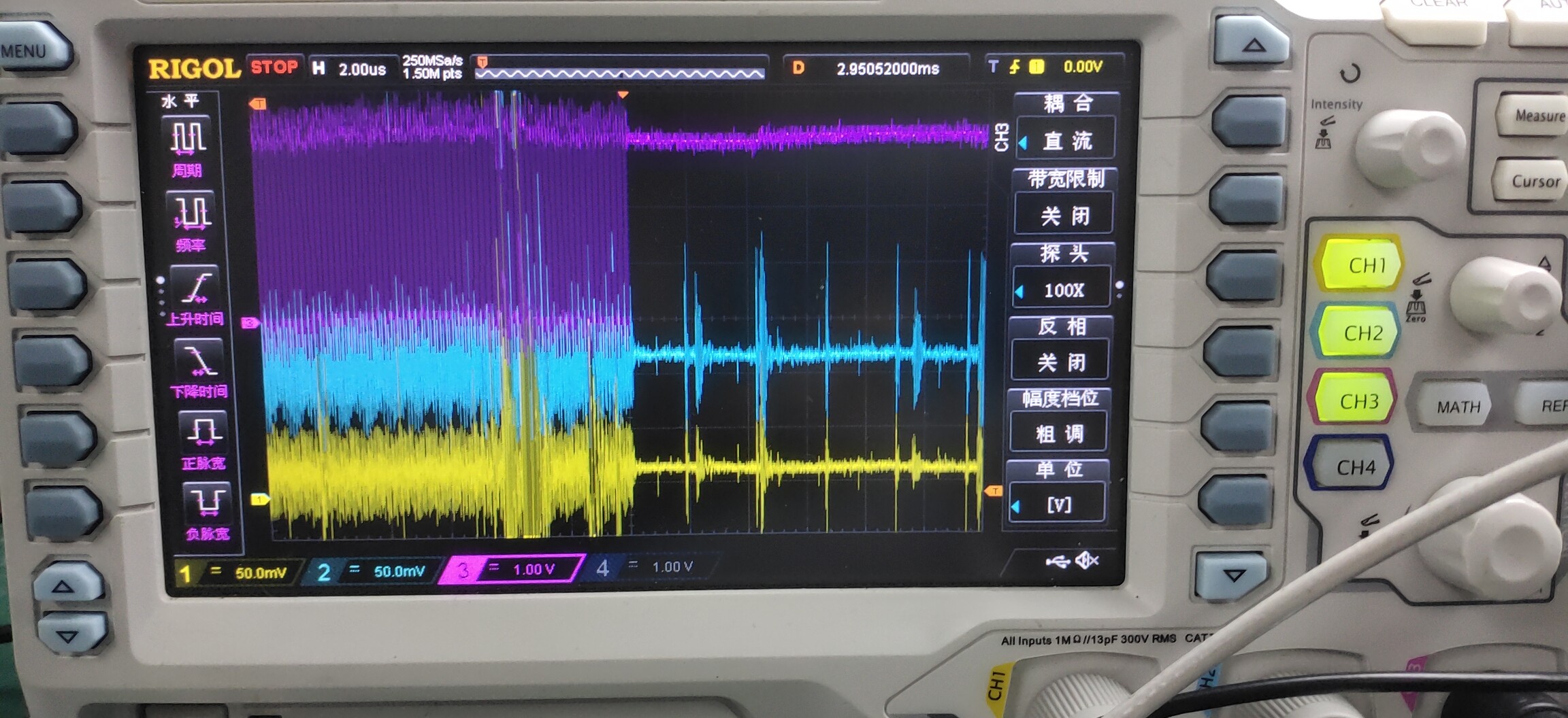
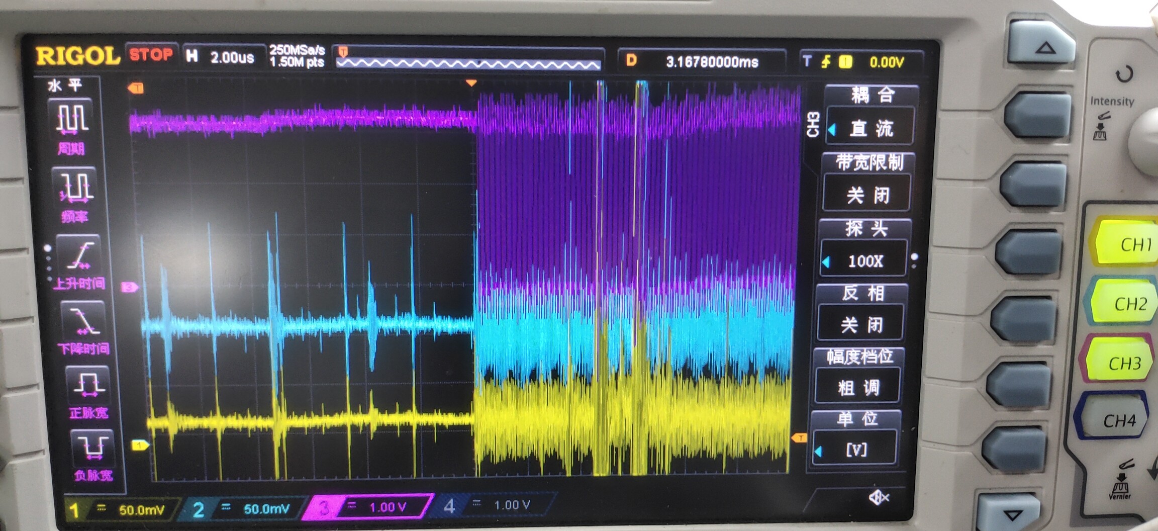
My customer is using the AMC1303M2510 for the in-phase current measurement in the servo drives. However, the device usually entered the fail-safe mode like the captured picture below:

you can the data out is hang on "1" before clock for 256 cycles (10MHz) , however, in the fail-safe mode, the CLK will hang on "1" for 70uS , is that correct ?

The device is in the fail-safe mode when the system is normally working , this is not we want to see because It will be false to drive the motor.

I checked the condition to trigger this mode :

a) The missing on the AVDD   b) The VCM > Vcmv (3V,  5V-2V)

My questions are:

1)  We checked the waveform of the AVDD , Vin+,Vin- with respect to the GND1, there is a little switching noise but is not sufficient to trigger the safe-fail mode ,

is there any factor to trigger this mode except for the two ones I listed?

2) We tried the value of the input capacitor on the AVDD , Vin+,Vin- as the datasheet recommended , but it has no effect. How to calculate the input capacitor to eliminate the common/differential mode noise effectively ?  

yellow: Data output    green: CLK out   Blue: phase current (DC current)

  • Hi Jason,

    The pictures you sent make some sense, the first one is the 256 cycles of the 10MHz internal clock of the AMC1303M2510 while the device is going into fail-safe mode.  Assuming this is the VCM fault, the device comes back into normal operation after the VCM level returns below VCMov (after ~70uS).  If it is because of AVDD failure, then it is taking 70uS for the voltage rail to recover.  Either way, it's a condition that lasts for at least ~96uS so I don't think it's a simple noise issue.  Can you provide more detail on how VINp and VINn are referenced back to AGND?  You can send me a note with better schematic snippets if you have them, the posted images are kind of hard to read. 

  • Hi  Tom:

    Thanks for your comments.

    I will give you the capture waveform to indicate the Vinp and Vinn and the clear schematic.

    One question , duration of the safe-fail mode depends on the time when the condition recover  rather than a fixed time, on the other hands, when the condition removed , the device will restore from the safe fail mode to the normal operation ?

  • Hi Jason,

    Yes - once the condition that caused the fail-safe mode to be activated is removed, the AMC1303 will go back to normal operation.

  • Hey Tom:

    Please check the below waveform recommend , in sight of the waveform , the device quite from the safe fail mode even the noise is exiting , that means this issue is not triggered by the noise on the Vin.

    1)  Enter the safe-fail mode :    Blue: Vinp to AGND   Yellow: Vinn to AGND    Purple: Dout 

    2)  Quit the Safe fail mode :

    3) Schematic: 

  • Hi Jason,

    What is the PV5U rail doing at the point when the fail-safe is happening?  You mentioned that you checked it initially, but do you have scope shots?

  • Hi Tom:

    I didn't capture the waveform of 5V rail, but i checked it before and make sure it's stable.

    Is there any factor trigger the fail -safe mode ? 

  • Hi Jason,

    Avdd and common mode input are pretty much the limits as to what can cause fail-safe mode to trigger.  This is a feature you won't find in some other parts.