Because of the holidays, TI E2E™ design support forum responses will be delayed from Dec. 25 through Jan. 2. Thank you for your patience.

This thread has been locked.

If you have a related question, please click the "Ask a related question" button in the top right corner. The newly created question will be automatically linked to this question.

ADC124S051: The ADC clock and the SCLK. What is a link?

Part Number: ADC124S051
Other Parts Discussed in Thread: CC1101

Dear specialists,

Is there somebody who can explain the following?

In the datasheet (page 10 for example) there is a text on the above: "FSAMPLE = 200 ksps to 500 ksps, FSCLK = 3.2 to 8 MHz, FIN = 40.2 kHz".

In the same datasheet one can find the text where it is written that the ADC starts conversion after 3d cycle of SCLK.

How can the ADC manage to covert an input signal if the ADC clock 16 times lower than SCLK (the last number can be calculated from the data)?

I'm trying to use ADC124S051 in some kind of voltmeter. If I measure a DC voltage I get a pretty result. If I try to measure an AC voltage the results are very inaccurate.

Thanks!

  • Hello,

    we have a great online video tutorial on ADCs available that can help further understand the functionality of a SAR ADC.

    I would suggest looking at TI Precision Labs, AS Specifications regarding your topic.

    In short, a complete conversion CYCLE is made of two phases, the acquisition phase and the conversion phase. A conversion CYCLE is the time it takes to complete both of these phases. a conversion CYCLE is how long it take to complete a conversion and decides the sampling rate of the device.

    In this device, the conversion PHASE starts after the third clock pulse. to complete a conversion CYCLE, 16 clock pulses are needed

    As for not being able to read a AC signal, what sampling rate are you running the device at?

    It has to be at least double of the input frequency to get correct readings. In this case, input frequency = 50Hz, thus sampling rate has to be >100Hz

    Would you share more specifics about the incorrect results or behavior you are seeing?

    Regards

    Cynthia

  • Thanks, Cynthia!

    Now I see.
    As usual the creators understand the subject very well, so they miss information that looks obvious.

    As for my project I use 1 Mhz SCLK. So I think it is enough :-) .

    The problem is while in conversion the very low frequency component appears. It looks like an AM-modulation or a superposition at least. That leads to error. "Baker's Best" explains that I have to change the input circuit. I will try this.


    Best Regards,

    Yourij

  • If you would like to share the inpur driving circuit, I can take a look at it for optimizations.

    The clock frequency does sound good. I will point out that the sampling rate is decided by CS, not SCLK though.

    What sampling rate are you running the device?

    What frequency is the analog input running at?

    Regards

    Cynthia

  • Hello!

    I suppose the driver circuit is not good. But firstly I'd like to ask about a feature that exists because I use an 8-bit controller to read the SPI.

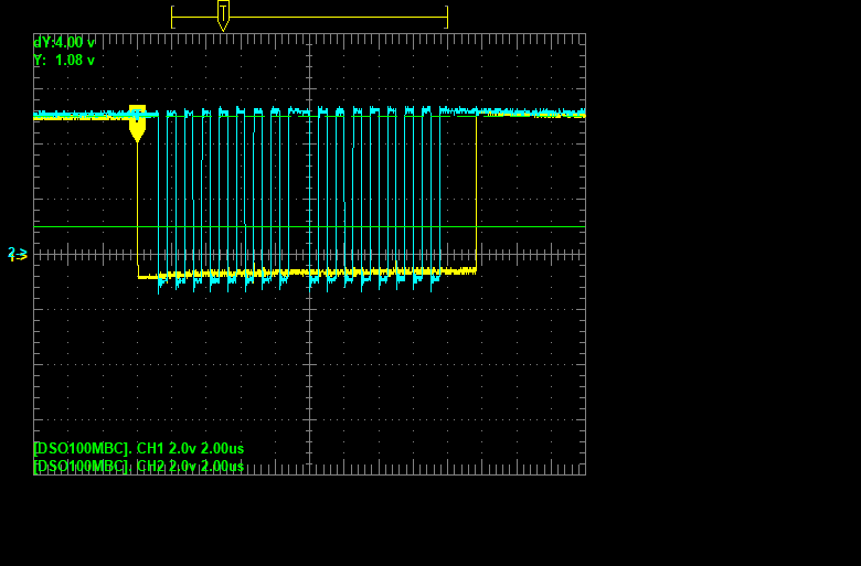
    The blue curve is SCLK, the yellow - CS. The data are read from low to high edge.
    As the SPI register has only 8 bit so I have to read an answer in 2 steps. So there is a gap in SCLK. When I used such method using CC1101, then it worked. I wonder if it can be a problem this case.

    I has tried to get an oscillogram that showed SCLK and DOUT but failed. When I connected one scope probe to SCLK and another to DOUT then ADC showed at least zero suddenly. I don't see why.
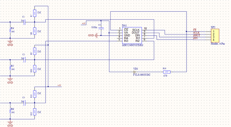
    Here is the circuit. It is rather simple. As I see from "Baker's Best" it would be better to insert a buffer stage.

    But can you explain a strange phenomena when a scope affects DOUT? I checked an input voltage, there was about 2.5 V. No AC.

  • What sampling rate are you running the device?

    What frequency is the analog input running at?

    The SDO line will be stable, which can be either high or low, until the device is converting. Do you see this behavior even after CS and SCLK are initiated?

  • The answer is in some posts ago. The sampling rate is 1 kHz (CS, look at the oscillogram), there is no any AC, look at the circuit, DC only, about 2.5 V at every of 3 inputs. That's all.


    One more time. I can check the SCLK, I can check SDO separately. But when I try to check both of them simultaneously the ADC shows wrong result. SDO drops to 1 or 2 "1" at the end of SDO sequence instead of "1" at 11th digit.

    And your last question, there is now any behavior after CS becomes high.

    And the last. The controller displays the data at the terminal and I can see the conversion result in a digital form.

  • Strange thing. Now the ADC works almost properly. There is some error in AC mode, but it looks like because of sampling rate.

    :-)

    I didn't receive any word concerning a variable SCLK.