This thread has been locked.

If you have a related question, please click the "Ask a related question" button in the top right corner. The newly created question will be automatically linked to this question.

TLV2372: if really need small capacitor and resistor or not

Part Number: TLV2372

Hi,

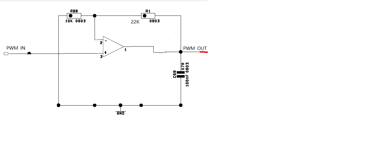
  Now use TLV2372(VDD=12V)to  enlarge high level voltage of pwm  from 3.3V to about 10.7V ,frequency range:1K--25KHZ

  1.Is it necessary to connect a small capacitor in parallel with R1?         if really need capacitor ,how much calculate capacitance value?

2.Is it necessary to connect a resistor in series between PWM_IN and positive input(pin3)?   if really need resistor  ,  how much calculate resistor  value?

Thanks a lot!


  • Hi Jacky,

    Placing a capacitor in parallel with R1 will help filter noise of your circuit. However, it will also slow down the rise/fall time of the signal because you will reduce the bandwidth of our circuit. My guess is that you probably will not want to slow down the signal for a PWM output. The recommended value depends on how fast you need the edge rates. The cut off frequency can be calculated as 1/(2*pi*R1*Cf). I recommend watching our TI Precision Lab videos on Bandwidth for more information.

    Placing a resistor between the input pins of the device (pins 2 and 3) will not provide any benefit.

    I highly recommend completely removing the capacitor on the output pin, C69, because this will only cause stability issues. It will NOT provide any filtering. I recommend watching our TI Precision Lab videos on Stability for more information.

    Thank you,

    Tim Claycomb

  • Hi,

       Regarding to resistor,You do not robably understand what my say

      The resistor is connected in series between PWM_IN and pin3 ,is not  connected in series   between pin2 and pin3 

       Regarding to small capacitance,it need place close to pin1 and pin2  or close to R1 in PCB  board?

    Thanks a lot!

  • Hi Jacky,

    I apologize for my misunderstanding. I think I understand now.

    A resistor is not required is series with PWN_IN and pin3 unless the PWN_IN amplitude will exceed the op amps power supply. If the input exceeds the power supply, the internal ESD diodes from the input pin to power supplies will turn on and conduct current. This current must be limited to less than 10mA to prevent from damaging the device. To limit the current a resistor can be used in series with the input.

    The capacitor in parallel to R1 should be placed as close as possible to the op amp IN- input pin as possible. Below are some technical articles on PCB layout of op amps that you may find useful.

    The Basics: How to layout a PCB for an op amp

    How to layout a PCB for high performance, low side current sensing

    Thank you,

    Tim Claycomb