Because of the holidays, TI E2E™ design support forum responses will be delayed from Dec. 25 through Jan. 2. Thank you for your patience.

This thread has been locked.

If you have a related question, please click the "Ask a related question" button in the top right corner. The newly created question will be automatically linked to this question.

CCS/ADS1282: How to do self-test mode in ADS1282

Part Number: ADS1282
Other Parts Discussed in Thread: ADS1284, ADS1281, ADS1283, DAC1282, ADCPRO

Tool/software: Code Composer Studio

Dear,

ADS1282 has two-channel multiplexer for signal measurement and ADC signal test.

How do I do the self-test modes? before the operation?

PS. There is a new ADS1284 ADC on the website with short datasheet only.

Where can find completed information and what is the different with ADS1282/1283? 

I will appreciate your help with this situation.

Regards,

YHH

  • Hi YHH,

    Here is a summary of the ADS128x product family evolution...

    ADS1281 - First device in ADS128x family.

    ADS1282 - Integrated a PGA & MUX.

    ADS1283 - Changed to a smaller package, reduced device's power consumption, added an internal offset to move idle tone, and added a /CS pin.

    ADS1284 - Added an optional reduced power mode (from 18 mW to 12 mW). SNR in the low-power mode is reduced by 3 dB. 

    There is a Request now link on the ADS1284 product page to request access to the full datasheet.

    (And here is link to request the ADS1283 datasheet Request now).

    I hope that helps!

  • Hello Chris,

    Thank you for the information.

    I already submit the request for datasheet. :)

    If I want to make a new design.

    Which is your recommendation?

    Regards,

    YHH

  • Hi YHH,

    Unless you have need for the lower power mode, I would probably consider the ADS1283, especially if you're planning to have more than ADC, in which case the added /CS pin makes communication between multiple devices easier.

    Also, I don't think I answered your first question about about performing self tests...The second MUX input is typically connected to a DAC1282 to exercise the ADC and connected sensor (a geophone, for example). The ADS1282 and similar devices aid in in self-testing through the integrated MUX, but the tests routines themselves are up to you to implement in the system design.

  • Hi Chris,

    I am not very clear the self test.

    There is only few words to talk about this.

    Do you have more detail or technical report?

    Regards,

    YHH

  • Hi YHH,

    Unfortunately, I don't think we have much collateral on this topic at the moment. This is more of a system design issue and isn't a built-in mode for either the DAC1282 or ADS1282.

    May I ask what kinds of testing your interested in performing?

  • Hi Chris,

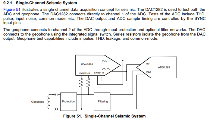
    I noticed the single-channel seismic system in the DAC1282 datasheet fig. 51.

    I don't know why DAC1282 VOUT connect to Switch In and Switch out connect to sensor route on the PCB.

    <a data logger for example>

    I think the test should be done before the logger installation. 

    Then ADS128x CH1 can be released for two channel measurement although CH1 and CH2 are not synchronized sampling.

    Or the values of impulse, THD, leakage, and common-mode test will change every time?

    So you do all of the test after power on?

    PS1. Do you have EVM of ADS1283/1284?

    PS2. I have ADS1281 and 1278 EVM board, But can't work in WIN10.

            Are they(ADCPro) support WIN10 now?

            There is no more update for a long time.

    Regards, 

    YHH

  • Hi YHH,

    The DAC1282 has a built-in switch to allow you to connect or disconnect the DAC from the sensor. This allows you excite the sensor and test the sensor's impulse response (for example).

    The second MUX channel of the ADS1282 is typically only used to connect to a test source, such as the DAC1282. Due to the settling time of the internal FIR filter, it is fairly impractical to alternate between the two ADC channels and get reasonable data throughput.

    The impulse, THD, leakage, and common-mode tests are generally directed towards testing the sensor's health. The ADC's performance is not likely to change much between uses, but since seismic data acquisition systems are exposed to the environmental elements, it is generally a good to have your system perform some self tests on a scheduled basis (such as on power-up) to test each channel and know if a sensor is perhaps damaged or out of place.

    Unfortunately, we do not have an EVM for the ADS1283 or ADS1284 at the moment. Alwo, we are in the process of updating some of our older EVMs to a software platform that is compatible with Windows 10, but for the meantime all we have are work around instructions that have allowed some people to get these EVMs to work with Windows 10 (See: https://e2e.ti.com/support/data-converters/f/73/t/779140).

  • Dear Chris,

    ADS128x has low-pass filter (FIR+SINC) and PGA.

    Do you recommend to use external low-pass filter and amplifier?

    Regards,

    YHH

  • Hi YHH,

    An external (passive) low pass filter is a good idea for anti-aliasing.

    NOTE: That the internal digital filter will perform most of the noise filtering; therefore, an external filter only really needs to provide attenuation for noise around "fMOD". At fMOD, the digital filter response repeats so the external RC filter should be sized to attenuate noise around these frequencies.

    Regarding the external amplifier, I would advise avoiding the use of an additional, external amplifier stage unless absolutely necessary. Usually the integrated PGAs inside delta-sigma PGAs are very low-noise and very high precision. Adding an addition amplifier tends to degrade the system's overall noise and accuracy performance. There are a few excepts to this, but the majority of discrete amplifiers will not perform to the same level as the integrated PGA.

  • Thank you Chris!!!

    In my case, the output voltage range of the sensor is -10VDC to +10VDC.

    But PGA has no gain less than 1, so I will use Voltage Divider (Kohm resistors) to fit the input range (-2.5VDC to +2.5VDC).

    Should I use buffer amplifier (voltage follower) after the voltage divider or not?

  • Hi YHH,

    The internal PGA has a high input impedance and will buffer the input signal (prior to the Delta-Sigma modulator), so you shouldn't need to use an external buffer.

    In order to measure a +/- 2.5V signal (after the voltage divider), make sure to use a 5V reference with the ADS1282.

  • Thanks Chris,

    I will try it after I get samples.

    Regards,

    YHH

  • Dear Chris,

    I'm sorry but I have a question about anti-aliasing filter.

    I need 100SPS for my system, so ADS128x is setting for 500SPS and I pick one sample every 5 samples (or the average of 5 samples). 

    According the thread (https://e2e.ti.com/support/data-converters/f/73/p/769869/2847226?tisearch=e2e-quicksearch&keymatch=low%20cut#2847226)

    "To prevent aliasing, you need to create a filter that goes out to fMOD/2, not fDATA/2"

    For ADS128x, fMOD = fCLK/4(High Resolution mode) = 1.024MHz

    The cut-off frequency of anti-aliasing filter should be 50Hz (fsample/2) or 250Hz (fDATA/2) or  512KHz(fMOD/2)?

    Regards,

    YHH

  • Hi YHH,

    The digital filter response will be mirrored around fMOD/2 and an additional filter passband will occur around fMOD. Therefore, any analog input filter should be sized to provide some attenuation (-20 dB or more) around fMOD +/- fDATA/2. Since fDATA << fMOD, this is effectively equal to fMOD, To achieve about -20 dB attenuation around fMOD, you should set the cutoff-frequency for a single-pole filter about a decade before this, so fMOD/10. It is okay to go lower, but do be careful, as I explain the consequences of very low cutoff frequences below...

    This is one of the added benefits of using an oversampling ADC, where the input sampling rate is much much faster than the output data rate. The anti-aliasing filter can be sized according to the higher-frequency sampling rate and not the slower data rate, and the internal digital filter provides the majority of the noise filtering. This greatly relaxes the design requirements on the anti-aliasing filter and often allows you use use a simple (and relatively small) RC filter for anti-aliasing.

    I would NOT recommend trying to design a passive RC filter with a cutoff frequency around 50 Hz!!. The R and C elements would be very large, slow to settle, have higher leakage currents, and the higher density dielectric material of the capacitor will also have a higher voltage coefficient (introducing distortion into the input signal). Try to use a C0G-type capacitor, as this is a very high quality dielectric (with a low-voltage coefficient of capacitance) that doesn't add much distortion to the input signal.

  • Thank you Chris.

    I will try to use 100KHz (fMod/10) cutoff frequency RC low pass filter. 

    R=1.5KOhm (Mouser Part # 667-ERJ-PB6B1501V)

    C=1nF (Mouser Part # 80-C0805C102J5G7210)

    Regards,

    YHH

  • Dear Chris,

    I would like to use ADC14 inside the MSP432P401R to measure the wind sensor in very low sampling rate. (<10Hz)

    Is it necessary to use an anti-aliasing filter?

    Regards,

    YHH

  • Hi YHH,

    I'm not very familiar with the internal ADC inside the MSP432P401R. Perhaps I can find someone else to comment on this.

  • Hi YHH,

    Unfortunately, I didn't have any luck finding someone to comment on this E2E thread. I would recommend asking your question in the MSP low-power microcontroller forum to see if someone monitoring that forum can help with this question.

  • Hi Chris,

    Thank you for your kind assistance.

    Regards,

    YHH