This thread has been locked.

If you have a related question, please click the "Ask a related question" button in the top right corner. The newly created question will be automatically linked to this question.

ADS1230: ADS1230 is behaving strange on 5V

Part Number: ADS1230

I am having a load-cell connected with ADS1230. ADS1230 is interfaced with 8bit STM8s controller. while operating system on 5V, ADS1230 is giving 0xFFFFF value, i'm not getting the conversion as per loadcell voltage changes. While operating on 3V3 voltage, everything is working fine. In my schematic I want to operate whole system on 5V instead of 3V3. I'm not getting what is going wrong.

I need to get it resolved as soon as possible. Any comments or guidance highly appreciated. 

  • Hi Taher,

    If you had the ADS1230 running at 3.3V, there is no reason why you should not be able to operate at 5V.  Do you have a schematic that I can review?  Are you operating both AVDD and DVDD at 5V?  Is the micro also operating at 5V? 

    Have you verified with an oscilloscope that the DRDY/DOUT pin is toggling at the selected data rate for the SPEED pin setting?  Is the PDWN pin high?

    Best regards,

    Bob B

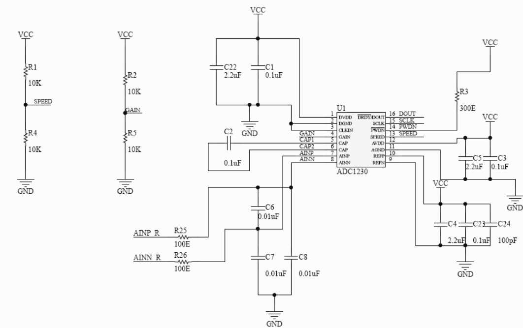
  • Dear Bob, Thanks for prompt response. Find my schematic attached here.

    PWDN PIN is connected to MCU and its high and externally pulled high as well. I will verify DOUT signals and will let you know.

  • Hi Taher,

    The PDWN pin is a bit tricky from the standpoint that it should remain low for at least 10us after AVDD and DVDD have reached nominal operating voltage.  This is illustrated in Figure 30 on page 19 of the ADS1230 datasheet. As you have a pullup (R3) on this pin most likely you will need to pulse the PDWN pin after the ADS1230 has started to make sure that the ADS1230 has reset properly on startup.  The PDWN low time must be at least 26us when pulsing the pin.  The value of R3 is shown as 300 Ohms.  I would suggest that this pullup be much larger in value (10k to 100k) as the micro would need to pull a lot of current to successfully pull the pin low.  For this pin it would actually be better to use a pulldown instead of a pullup when using a micro to control the pin.

    You should always issue the offset calibration after power-up and after pulsing the PDWN pin.  This is accomplished by sending at least 26 SCLKs to the ADS1230.  Offset calibration is described on page 16 of the ADS1230 datasheet. 

    I assume that you use R1, R2, R4 and R5 for configuring the device.  You should not have all four resistors populated.

    Best regards,

    Bob B