This thread has been locked.

If you have a related question, please click the "Ask a related question" button in the top right corner. The newly created question will be automatically linked to this question.

ADS5296A: after init, sometimes ads5296 get digital noise. test pattern is ok

Part Number: ADS5296A
Other Parts Discussed in Thread: ADS5296

after init: some fix chan has digital noise: the analog input is zero, but the adc output has some bit has err '1'.

power on the system 6 times, get 1 err init result probably。

the top channel is ok, but the below channel has some err. the analog input is same. when i switch to the test sync pattern or deskew pattern, the result is ok,

like the picture below.
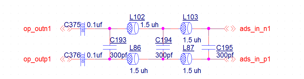
below is my design:

  • Thanks for using TI part! 

    This issue could be LVDS timing or ADC sparkle code. 

    Since the test pattern is OK, we assume the LVDS timing is fine. please also configure the device into the RAMP mode to check all bits are OK. normal RAMP pattern can exclude the LVDS timing completely. 

    if LVDS timing w/ RAMP test is OK, we would suggest check whether this issue happens on another board. or you can replace the device on PCB and see whether the issue follow the PCB or follow devices. typically a A B A swap test would do.  it could be possible some operation conditions trig sparkle code. replacing a device can solve the problem. 


    Thanks!

  • thanks for your reply.

    first, when the err bit occur, I switch to the SYNC pattern and the RAMP pattern, get the right and steady result, so I thick the digital part is right.

    second, this happens on many board with different channels. and whihin one board, the err channel is fixed, the good channel will never get err bit.

       I will try to switch the ads5296 on two borad.

    third, I find that, when the err channel happen, if keep the board power on, I must soft reset the adc and re adjust lvds timing to recover the err channel.

    without soft reset the adc, the err never recover.  If just soft reset the adc and set 10bit mode( which I use ), it will use 5 times reset to recover the err channel,

    Does the phase between the bit clock and the lvds change after reset?

  • I also want to know the regs MUST be inited to get the adc work fine.

    I just use 0x00, 0x25, 0x46, 0x45, does it enough?

  • Jie, 

    based on the finding you have, "third, I find that, when the err channel happen, if keep the board power on, I must soft reset the adc and re adjust lvds timing to recover the err channel."

    look like it may be a LVDS timing vs. temperature. typically system will need to retuning LVDS timing quite often, since temperatuer change affects the LVDS timing.  hope only retiming the LVDS can solve the problem. 

    the inititalization procesdure is shown as below.  then you can write  your registers.  

    Thanks!

    Register Initialization
    After power-up, the internal registers must be initialized to default values. This initialization can be accomplished
    in one of two ways:
    1. Either through a hardware reset by applying a low pulse on the RESET pin (of widths greater than 50 ns),
    see Figure 74; or
    2. By applying a software reset. When using the serial interface, set the RST bit (register 00h, bit D0) high. This
    setting initializes the internal registers to default values and then self-resets the RST bit low. In this case, the
    RESET pin is kept high (inactive).

  • We find that, the analog input circuit will affect the err channel.

    we use ad8330 to drive the ads5296, whos output res is 15o om(differential),

    between the ad8330 and the ads5296 is a low pass filter as below

    and my pcb is as below,

    Does the hardware have some problem?

  • i don't see the analog circuit has issue. the mismatch of inductor may affect the filter response, while it should not affect the wrong code, which can be fixed by LVDS timing tuning. 

    wehther the LVDS timing tuning can fix the problem is the key. this will tell us the problem is analog or digital LVDS timing. 

    Thanks!

  • Must soft reset the adc. it will take 1 or 2 times soft reset with lvds retiming to recover,  take 5 to 7 times soft reset without lvds retiming to recover.

  • Jie, 

    when you say the analog amplifier affects the noise, what did you do and what effects you have?  you said the output impedance is 150ohm, do you have termination resistors at the ADC side? 

    did you try the hardware RESET in the all tests? i saw your sch has RESET pin is floating. maybe you can try a blue wire and see. 

    Thanks!

  • I have one board, when the analog amplifier's gain is high( > 30db ), the err bit happens.

    Don't have termination at the adc side, between the amp and the adc, only have the low pass filter.

    I have tried the hardware RESET, just the same.

  • Thanks Jie!

    high gain means higher signal amplitude. did you measure the highest signal amplitude at ADC inputs? maybe you can add the back to back diodes at the amplifier outputs to limit the ADC input as 2Vpp to 3Vpp. This way, the overload to the ADC is not much. 

    Thanks! 

  • I only find one board like this, other boards don't have this problem. so I think the hardware around the adc affect the adc, when I init the adc and sample the analog signal.

    I will have ten boards with smt, after some days, I  will check the problem then.

  • I may try that diode.

    After some days, we will have some more boards, I will statistic then.

  • Jie, 

    Thanks!

    we will wait for your results from more boards.  you can also leave your email and we can have more specific discussion off line. Thanks! 

  • hi, my email is zhujie358@live.com.

  • Thanks! we will move the discusson offline for more details.