This thread has been locked.

If you have a related question, please click the "Ask a related question" button in the top right corner. The newly created question will be automatically linked to this question.

ADS131E08: Issue during reading multiple channels

Part Number: ADS131E08
Other Parts Discussed in Thread: ADS131E04

Hello,

I run communication with ADS131E08 device using 12.5 MHz SPI. Below are sources:

= Initialization source =

/* AFE configuration */
IO_SETCLR(AFE_CS|AFE_PWDN|AFE_RST, AFE_START);

/* Meet tPOR (> 2^18 tCLK ~ 130ms Wait after power up until reset) */
archDelay(65000);
archDelay(65000);

/* Device reset */
IO_CLR(AFE_RST);
archDelay(50); /* Meet t_RST (> 1 tCLK ~ 0.5 us Reset low duration) */
IO_SET(AFE_RST);
archDelay(900); /* Meet t_RST (> 18 tCLK ~ 9.0 us until device start) */

/* Device initialisation */
_WrCmd(SDATAC); /* Stop read data continuous mode */
_WrReg(CONFIG1_REG, 0b11010011); /* 24-bit output, 8 ksps */
_WrReg(CONFIG2_REG, 0b11110100);
_WrReg(CONFIG3_REG, 0b01000000); /* power down internal reference */
_WrReg(CH1SET_REG , 0b00010000);
_WrReg(CH2SET_REG , 0b00010101);
_WrReg(CH3SET_REG , 0b00010101);
_WrReg(CH4SET_REG , 0b00010101);
_WrReg(CH5SET_REG , 0b00010101);
_WrReg(CH6SET_REG , 0b00010101);
_WrReg(CH7SET_REG , 0b00010101);
_WrReg(CH8SET_REG , 0b00010101);

/* Start conversion */
IO_SET(AFE_START);

_WrCmd(RDATAC); /* Enable read data continuous mode */

= /DRDY Interrupt service routine =

/* read status */
IO_CLR(AFE_CS);
status = _RdStat();

/* read channels */
afe_val[0] = _RdChan24Bit();
afe_val[1] = _RdChan24Bit();
afe_val[2] = _RdChan24Bit();
afe_val[3] = _RdChan24Bit();
afe_val[4] = _RdChan24Bit();
afe_val[5] = _RdChan24Bit();
afe_val[6] = _RdChan24Bit();
afe_val[7] = _RdChan24Bit();
archDelay(200); /* Meet t_SCCS (> 4 t_CLK ~ 2.0 us before CS=1) */
IO_SET(AFE_CS);
archDelay(100); /* Meet t_CSH (> 2 t_CLK ~ 1.0 CS=1 pulse duration) */

==

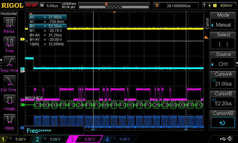
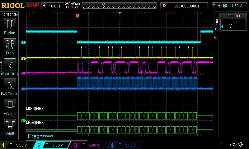
Channels 1-4 are read correctly, reflecting external applied voltage and/or test signal, 5th channel is moreless a constant value and channels 6-8 are values applied on channels 1-3. Seems like reading takes longer but it is not the case @ 12.5 MHz SPI clock (checked on scope). I plan to investigate more but hope you might have seen it already and able to provide some thoughts on what to try.

Thanks,

Martin M.

  • Martin,


    If the latter reads of data when you are expecting channels 6-8 are coming back as the reads from channels 1-3, then you may be mis-timing the reads from the ADCs based on the completion of the conversion.

    When the ADCs are converting, they put data out periodically based on the data rate. Once the conversions are completed, they should be read immediately and the read should be completed before the next set of conversions are done.

    In your case, you may be reading the conversion for the first 4-5 data and then a new set of conversions complete. At that point DOUT is loaded with new data and it starts over again with reads from channels 1 to 3 as you finish your read. Your read is interrupted by the device when it gives you another set of conversion data.

    You can check this out with a logic analyzer or oscilloscope. Look at read of the 8 channels and see if /DRDY is indicated after the 5th read.

    This is my best guess on what you're seeing. If this doesn't pan out, post back and we can continue working on it.


    Joseph Wu

  • Hi Joseph,

    thanks for your response.

    I have performed measurements using internal test voltage "(AVDD+AVSS)/2" applied on all channels:

    Here is configuration:

    _WrCmd(SDATAC); /* Stop read data continuous mode                     */

    _WrReg(CONFIG1_REG, 0b11010011); /* 24-bit output, 8 ksps             */

    _WrReg(CONFIG2_REG, 0b11110100);

    _WrReg(CONFIG3_REG, 0b01000000); /* power down internal reference     */

    _WrReg(CH1SET_REG , 0b00010001);

    _WrReg(CH2SET_REG , 0b00010001);

    _WrReg(CH3SET_REG , 0b00010001);

    _WrReg(CH4SET_REG , 0b00010001);

    _WrReg(CH5SET_REG , 0b00010001);

    _WrReg(CH6SET_REG , 0b00010001);

    _WrReg(CH7SET_REG , 0b00010001);

    _WrReg(CH8SET_REG , 0b00010001);


    And measured the following SPI waveforms on the oscilloscope:

    Channel 1 = /DRDY

    Channel 2 = /CS

    Channel 3 = DOUT

    Channel 4 = SCLK (3.125 MHz)

    Note that /DRDY pulse occurs every 125us (8kHz).

    Detail of reading status + first 5 channels:

    Note that returned values are small negative but 5th channel value is more less constant 0xc08000 and it is a wrong value. If I continue reading 9th channel (doesn't exist) then I read small negative value. 


    Detail of SPI communication:


    Below is ADS131E08 device connection on our PCB:


    Any suggestions please on what else to try?

    Just read on datasheet that DAISY_IN shall be grounded - will try it tomorrow.

    Thanks,

    Martin M.


  • Martin,


    Thanks for the scope plots and the schematic. They do help narrow down the problem.

    Here are a two things to look at:

    First can you show a plot of the RDATA command and the following result? There should be enough resolution so that I can see the RDATA command and the resulting data. You may need take trigger the scope for the read and then adjust the time division to see the command and the 216 bits of information. I want to ensure that there is one RDATA command, and then DIN is held low for the duration of the device channel reads.

    Second, make sure that the timing is followed as shown on page 61 in the datasheet. This is described in the Power-up Timing section. My concern here is that if the power-up is not correct, the device may think it is programmed as an ADS131E04 four-channel device instead of an eight-channel device. This may explain the good results for four channel reads. I would also review Figure 53 describing the Initial Flow at Power up.

    It might also be useful to read through all the registers (including the ID register) just to make sure that the device is responding correctly.


    Joseph Wu

  • Hi Joseph,

    thanks for suggestions on what else to check. Haven't checked everything you suggested yet but captured MOSI signal from MCU during reading channels. The MOSI signal is driven high when in idle, but results in 0x00 SPI command received by ADS – see below:

    Channel 1 = DIN

    Channel 2 = /CS

    Channel 3 = DOUT

    Channel 4 = SCLK (3.125 MHz)

    Can this be a root cause of the problem?

    Note that I cannot change MOSI output polarity in idle mode easily on MCU level but have to add an external invertor on PCB to fix it - therefore asking for opinion first prior making PCB changes.

    Kind regards,

    Martin M. 

  • Dear Joseph,
    I did check power up sequence and found no deviation in timing. I addition, software now reads Id control register after SDATA; device returns 0xC0 {4 channel device, 4th bit not asserted!} - see below:

    Please, what exactly might drive device to think it is a four channel device vs. eight during power up sequence?  

    Kind regards,
    Martin M. 

  • Martin,


    The ADS131E08 has a set of internal registers (not user accessible) that allow for setting the device configurations that are programmed during our final test. These register are used for programming the functionality and characteristics of the device.

    During the power-up, there is generally a power-on reset that allows for time for the supplies to settle to the final value and then acquire the configuration from the registers. However, if the power supply doesn't come up correctly, this power-on reset may not execute properly and the internal registers may not be correctly read. If this happens, then the device may appear that it is programmed as the four-channel ADS131E04 instead of the eight-channel ADS131E08.

    To be sure, I would go through the power-up sequence in the datasheet, and ensure that there is a reset of the device, so that the device goes back to read the internally programmed registers.


    Joseph Wu

  • Dear Joseph,
    the problem seems to be external pull down resistors on /PWDN and /RESET inputs. Even MCU takes longer then 130ms to power up the tPOR time of the ADS131E08 starts after /PWDN and /RESET inputs set to 1 in SW. Adding additional 130ms delay after setting /PWDN = /RESET = 1 in SW resulted in ADS131E08 device to boot in 8channel mode. Havign said that I will change external pull downs on those two pins to external pullups and therefore also portion of MCU initialization will be included in tPOR time achieving faster application startup. 

    Thanks a lot for your support and please consider this issue as solved!

    Kind regards,
    Martin M.

  • Martin,

    I'm glad you were able to get the system up and running. If you have any questions feel free to post back with any questions.


    Joseph Wu