This thread has been locked.

If you have a related question, please click the "Ask a related question" button in the top right corner. The newly created question will be automatically linked to this question.

TLA2024: I2C communication failed - no response from TLA2024 over I2C line.

Part Number: TLA2024
Other Parts Discussed in Thread: ADS1015

I am using TLA2024 to measure differential voltage between AIN2 and AIN3 with following parameters:

ADDR - > GND - Slave address(48h)

VDD - 5V

I2C bus pull up resistor - 10k Ohm

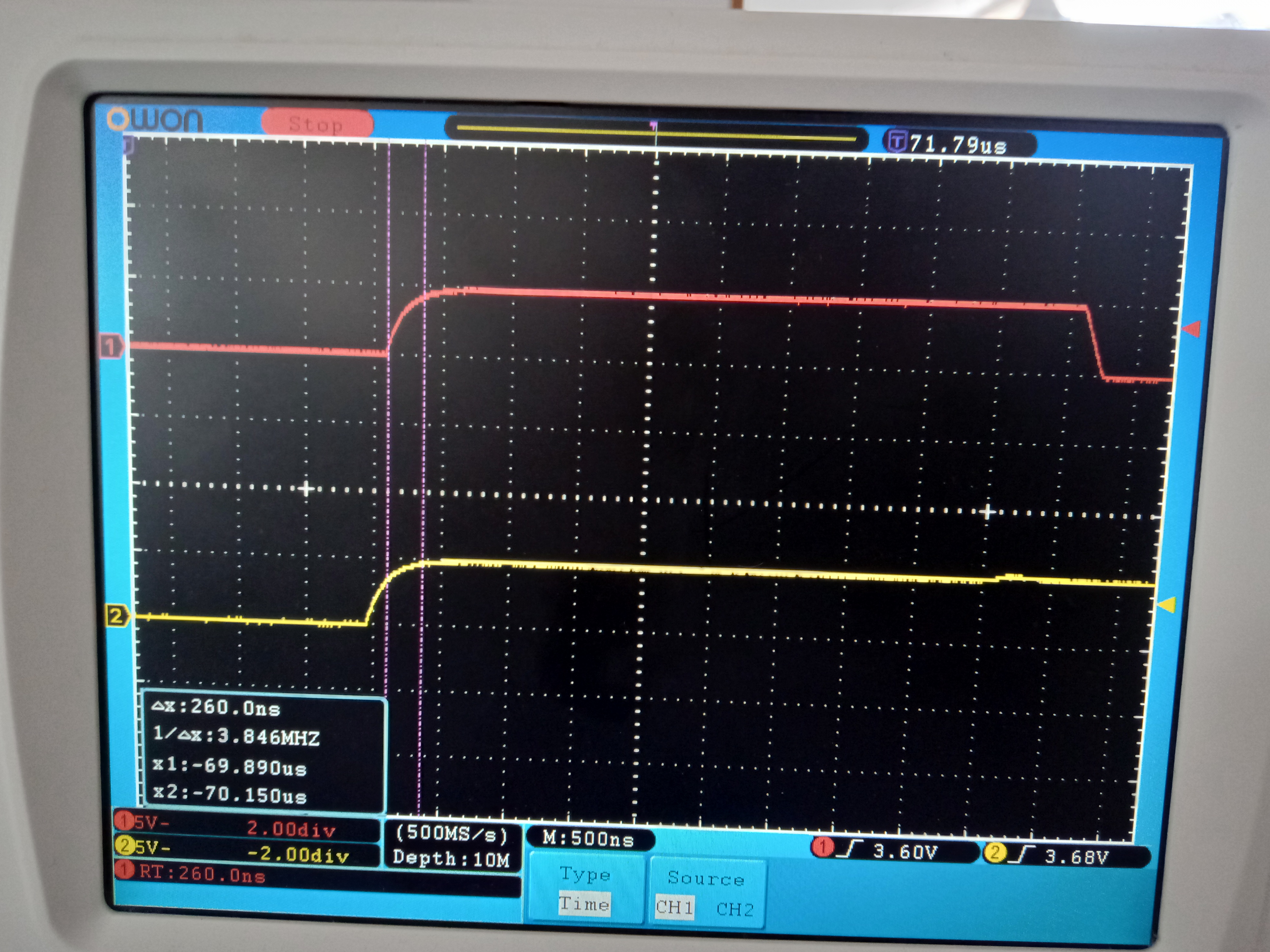
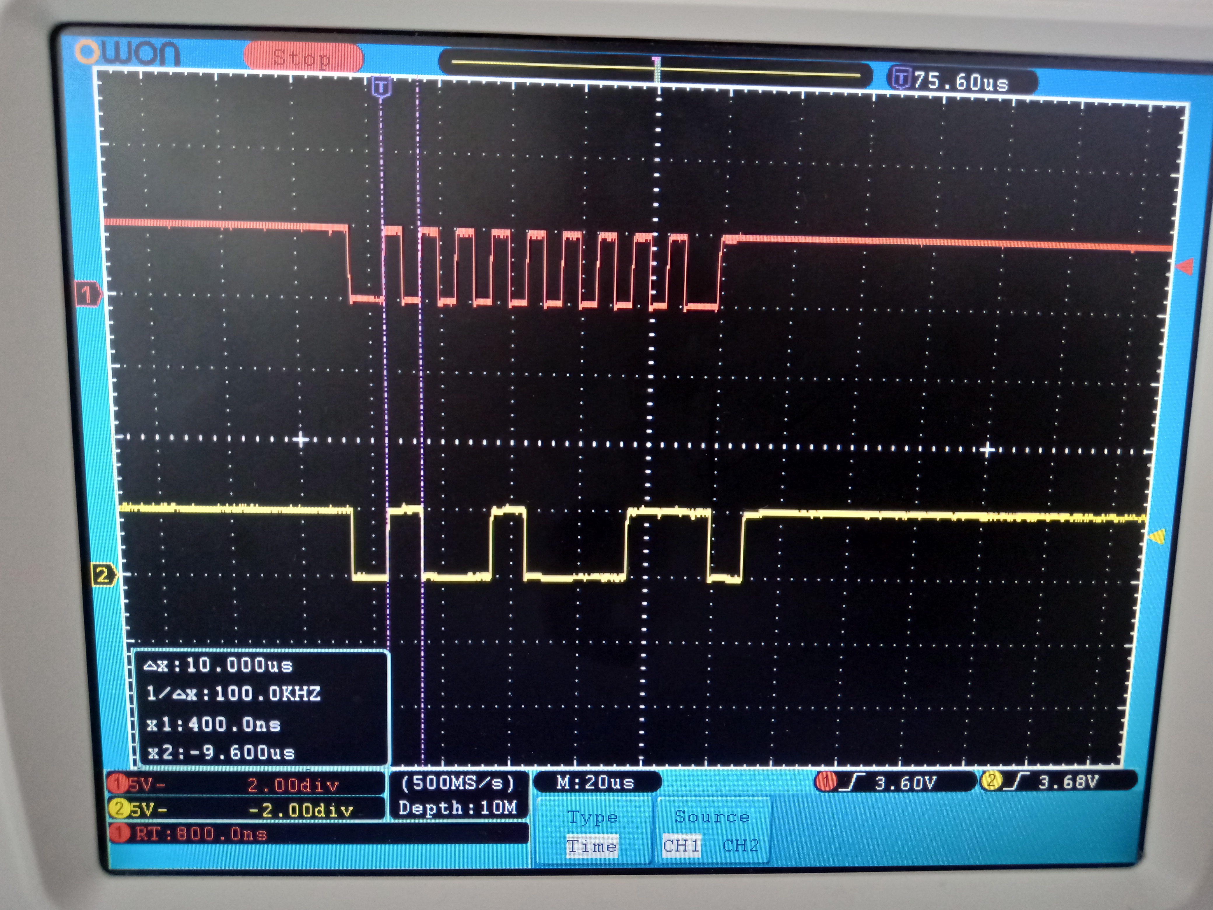
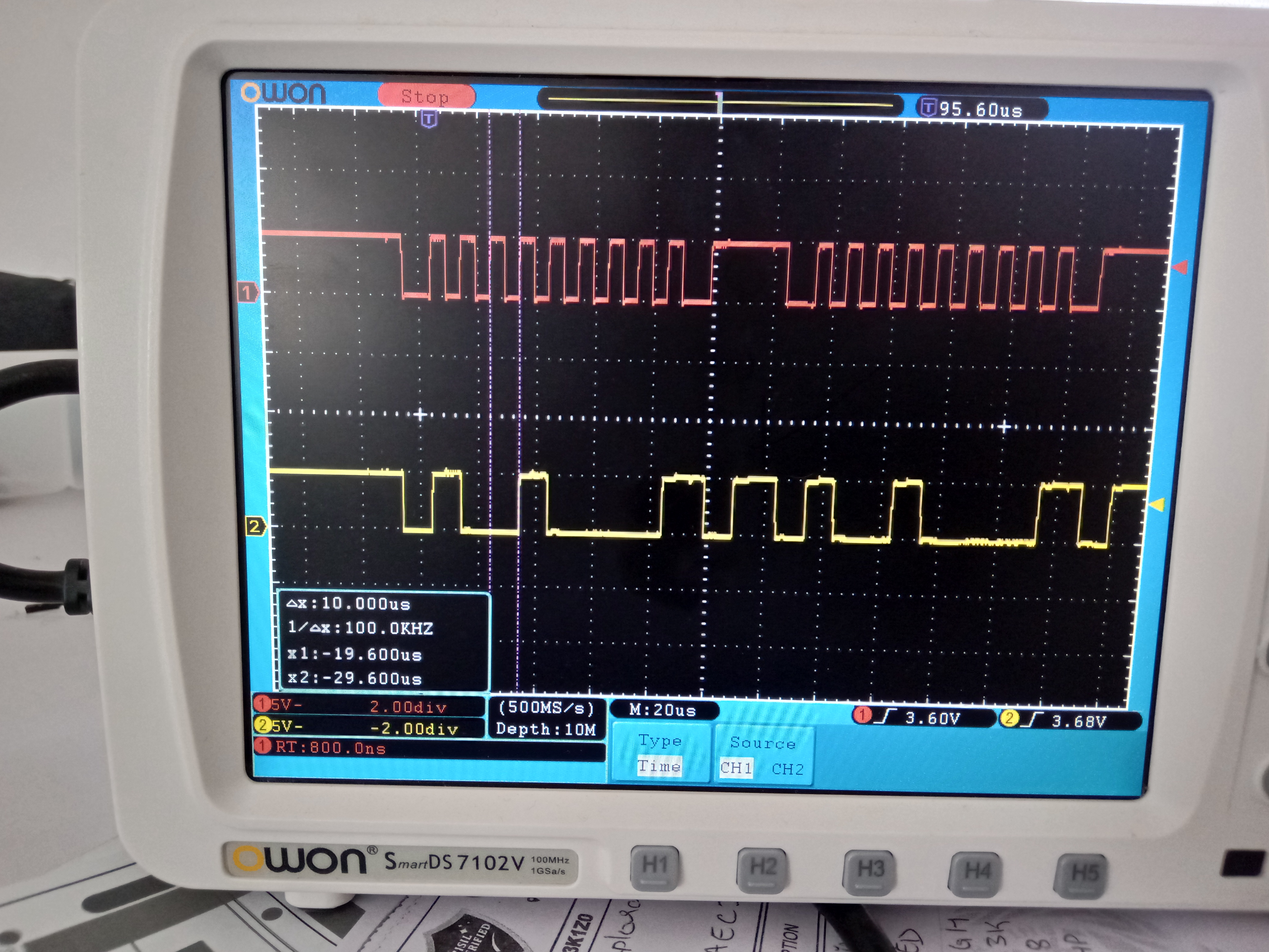
I2C bus clock frequency - 100kHz

9th clock is too slow. Also, TLA2024 doesn't acknowledge, we get NACK on the 9th clock.

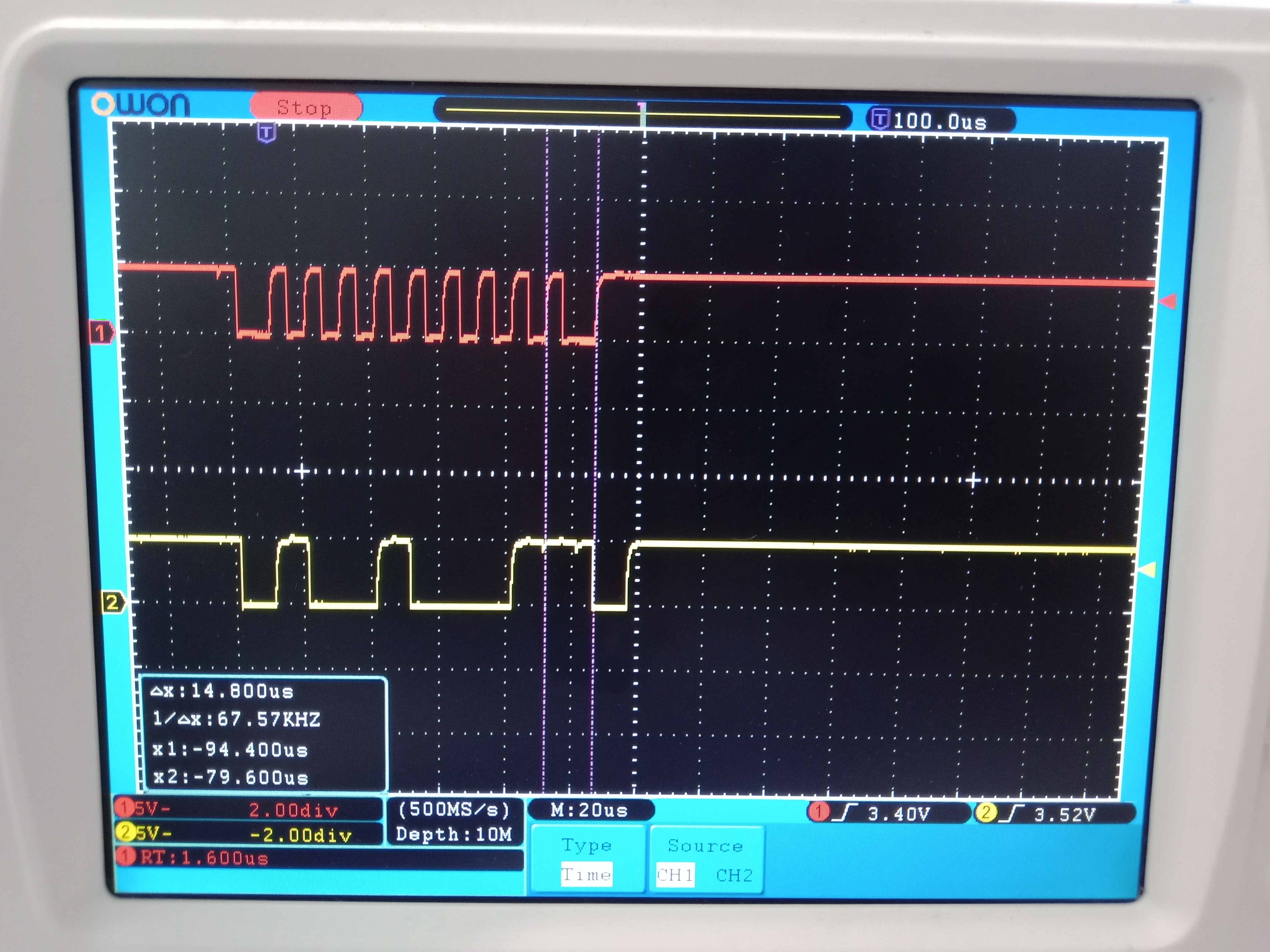
There's no response from the TLA2024 when I tried reading the config register.

Also, I can't write to the TLA2024's config register. 

Please help me out.

Regards,

Nishil Bhavsar

  • Nishil,


    Thanks for posting your scope photos of your I2C communications. Normally this is what we'd have you post to identify communication problems. However, there isn't anything that is plainly obvious that is wrong. The I2C address is correct, but it looks like the device is not responding.

    However, there are plenty of things to check. I would start with the schematic. Post it back here just so I can have a quick look. Make sure that the SDA, SCL and ground connections are all correct from the microprocessor to the device. I would also verify the ADDR pin connection.

    One thing to check is to see that the communication follows all the I2C timing requirements on page 6 of the device. The one thing that might be an issue from your post is that the SDA rise time is a little slow. The timing requirements say that the max rise time is 1000ns, and you might be a bit to slow based on the scope photos. To help make this faster, I would use a lower resistance for the pull-up. Switch out the 10k resistors for 2k and see if this speeds up the rise time. However, be sure to review the other timing requirements.


    Joseph Wu

  • Joseph,

    Thanks for posting your scope photos of your I2C communications. Normally this is what we'd have you post to identify communication problems. However, there isn't anything that is plainly obvious that is wrong. The I2C address is correct, but it looks like the device is not responding.

    Yes, that's why I am concerned why the I2C communication isn't working?!


    However, there are plenty of things to check. I would start with the schematic. Post it back here just so I can have a quick look. Make sure that the SDA, SCL and ground connections are all correct from the microprocessor to the device. I would also verify the ADDR pin connection.

    Verified SDA, SCL and GND connections. They are okay. ADDR pin connected to ground.


    One thing to check is to see that the communication follows all the I2C timing requirements on page 6 of the device. The one thing that might be an issue from your post is that the SDA rise time is a little slow. The timing requirements say that the max rise time is 1000ns, and you might be a bit to slow based on the scope photos. To help make this faster, I would use a lower resistance for the pull-up. Switch out the 10k resistors for 2k and see if this speeds up the rise time. However, be sure to review the other timing requirements.

    Changed the pull-up resistor from 10k Ohm to 2.3k Ohm. The rise time now is 280 ns.

    Uploading the same communication sequence but with 2.3k Ohm resistor

    Again there's NACK from TLA2024. Why is this happening?

  • Nishil,


    The first thing that I would check is the mounting of the device. The RUG package is very small and difficult to solder. I would check to see if there are any solder bridges between any of the pins. Even then visually inspect all the connections to the pads from the side.

    Other than that, I'm not sure why the I2C communication isn't working for you. I did see the schematic clip out that you sent. Can you send the full schematic? It might be helpful to see it in its entirety. Also, if you are breadboarding the connection between the microprocessor and the board, can you show where the connections are on the schematic and perhaps a photo of the setup? This device's interface is the same as several in the product line and I've experimented with some quick communications.

    In the past I've made similar connections to the ADS1015 (which again has the same interface as the TLA2024). I did outline the connections and showed scope shots in the following post:

    e2e.ti.com/.../1505842

    In that example, I connected the SDA, SCL and ground and ran power from the master's power supply to match the +5V VDD. Then I ran the controller to communicate with the device. I would read through that post and see if it helps. Unless the device is damaged, the communication should be fine.


    Joseph Wu

  • Nishil,

    I haven't heard from you for a while, so I thought I'd check in on your I2C communication problem. In my last post, I suggested that you should check the soldering on the device and recheck the connections from microprocessor to the device.

    I'll close this post for now, but if you haven't found a solution, post back here and we'll continue to work on this issue.

    Joseph Wu