This thread has been locked.

If you have a related question, please click the "Ask a related question" button in the top right corner. The newly created question will be automatically linked to this question.

ADS1015-Q1: Alert function issue

Part Number: ADS1015-Q1
Other Parts Discussed in Thread: ADS1015

Dear Expert,

My customer would like to design ADS1015 with Alert function, but cannot trigger the threshold they setting.

May I have your feedback about this?

Below is customer's register setting.

00: conversion register -->0xe046

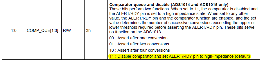
01: configure register--> 0xa8c3

02: lo_thres register --> 0x0010

03: hi_thres register--> 0x0020

Regards,

Ben


  • Ben,


    Looking at the configuration register that you've provided, you set it to A8C3. This means that the last two bits (COMP_QUE[1:0]) are set to 11. This disables the comparator:


    The customer should set the configuration register to A8C0 to assert the comparator after one conversion. Have them try this and see if it works.


    Joseph Wu

  • Dear expert,

    We have tried to set COMP_QUE as 00, but still cannot trigger to H/L threshold of comparator.

    The last register setting from customer as below.

    00: conversion register --> 0x46e0

    01: configure register--> 0x43a8

    02: lo_thres register --> 0x1000

    03: hi_thres register--> 0x2000

    Regards,

    Ben

  • Ben,


    If the comparator alert is not working there are several things to check.

    1. The ALERT/RDY pin requires a pull-up resistor, similar to the SDA and SCL lines. Make sure that the circuit has this installed. The alert is active low.

    2. Make sure that the threshold is correctly being programmed. Read back the Hi_thresh and lo_thresh registers have been programmed to the new values.

    3. Test out different values for the threshold. I would set the lo_thresh to be 7FF0h. This would trigger the comparator on every single conversion. Really, I would like to see the comparator trip for any valid input.

    After that, I'd like to see the schematic for the circuit. There might be some other problem with the hookup for the device. I would also like to see and scope shots or logic analyzer outputs to check the digital communication.


    Joseph Wu