This thread has been locked.

If you have a related question, please click the "Ask a related question" button in the top right corner. The newly created question will be automatically linked to this question.

ADS1278EVM-PDK: Evaluation board seems to boot ok, but no measure is done

Part Number: ADS1278EVM-PDK
Other Parts Discussed in Thread: ADCPRO, ADS1278

Hello,

We have purchased ADS1278EVM-PDK evaluation board and tried to test it connected to computer using ADCPro software.

It seems it recognizes the board properly and boots MMB0 DSP ok, but when trying to acquire it shows nothing.

The steps we have done:

1. Prior to connect it, we read ADS1278EVM user’s guide (also ADCPro guides), and followed all steps, checking that all jumper configuration was as default. Then, we installed software required (including driver).

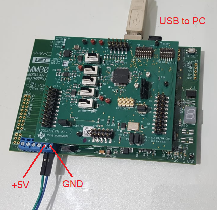
After that we connected power (+5V) as it is described on ‘ADCPro Hardware and Software Installation Manual’:

With board powered on, we connected USB to computer. Power and USB were the only connections done to the board, as shown on following picture:

2. We run ADCPro software and selected from menu: EVM ADS1278EVM.

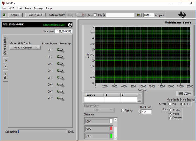
After some (green) messages it shows ‘Connected to EVM’, and I see 1-2-7-8 sequence on 7-segment display of MMB0.


3. Select from menu: Test MultiScope.

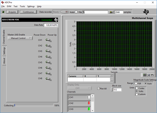
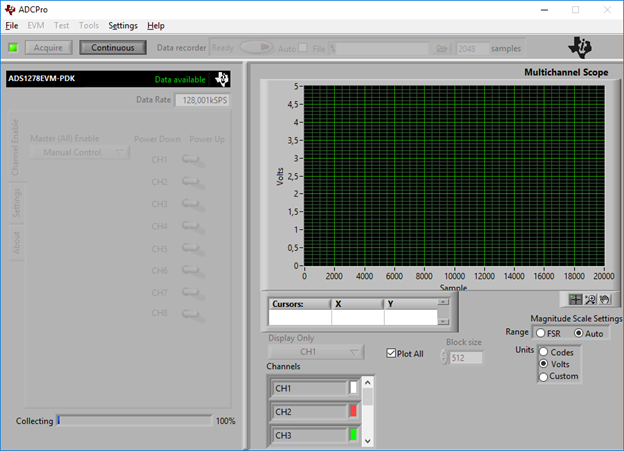
4. Clicked on ‘Acquire’, and after some fast green text messages it shows ‘Connected’, but no measure is shown:

I also tried by clicking on ‘Continuous’, but it keeps in the following state until I click on ‘Continuous’ again:

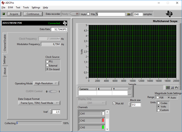
I’ve tried changing Clock Source, from PLL to ‘On-board’, and operating mode, but always same result, no measure is shown:

All four voltage leds indicators are turned on in MMB0 (+5V / +1.8V / +3.3V / +1.6V).


After doing a few tries, by reconnecting USB, power off/on, etc. I noticed that ADS1278EVM daughter board was hot, so I measure current consumption with daughter board connected and disconnected:

  • MMB0 only (ADS1278EVM disconnected): 190 mA
  • MMB0 with ADS1278EVM connected: 840 mA


Maybe I am wrong, but I think that the current consumption difference that appears while connecting EVM card is very high for this board, so I suspect that there is something wrong/damage with the ADS1278EVM daughter board.

Or am I doing anything wrong?

Thanks for any help!

Best regards,

Alejandro Panelli

  • Hello Alejandro,

    It appears that the ADS1278EVM board has been damaged; current consumption should be less than 400mA when taking readings.  However, double check the alignment of the three connectors between the MMB0 and ADS1278EVM boards just to be certain the boards are properly mated to each other.

    Is it possible you accidentally applied more than 5.5V to the board or you hot connected the supply?  The MMB0 board has voltage regulators that can take at least 6.5V or more for a transient, but the ADS1278EVM routes the 5V directly to the ADS1278, input amplifiers and reference which makes it more sensitive to transients.  When applying power to the barrel connector on the MMB0 board, it is fed through a 5V regulator that can tolerate >10V on its input.

    I checked the supply current on the EVM.

    • MMB0 connected, ADS1278 in power-down:  190mA
    • MMB0 connected and ADS1278 powered up and sampling:  380mA

    Although this would not cause high current consumption, double check that all of the dip switches are in the down position, and verify all of the jumpers and slide switches are in the proper position per Figure 1 in the user's guide.

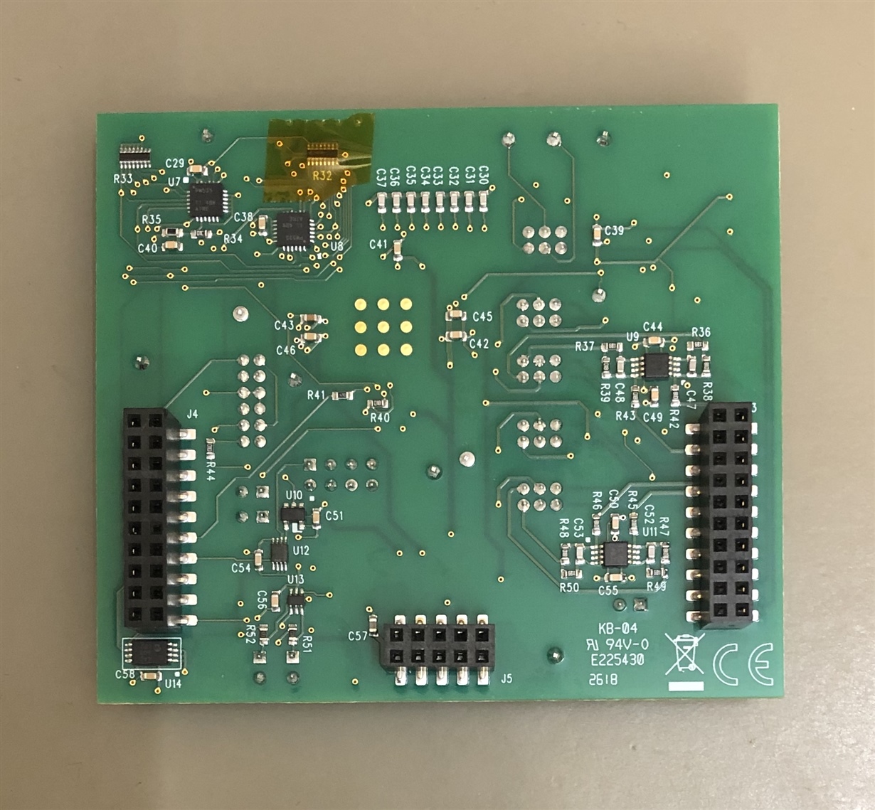
    Also, on the bottom side of the ADS1278 board, there should be insulating tape covering R32.  This prevents shorting to the USB connector shell on the MMB0 board.

    Regards,
    Keith Nicholas
    Precision ADC Applications

  • Hello Keith,

    Thanks for your response.

    I have checked the alignment of the three connectors between boards and they mate properly.

    About power supply, I am using a +5V switching power supply with soft start, that I use in a lot of boards without any problems, it never burnt any IC, and I have never seen values/peaks above +5V.

    I also checked dip switches and jumper position, and all are as the figure you sent.

    The insulating tape looks good, it does not seem damaged.

    I took a multimeter and measured conductance/resistance between powers supply pins and GND on J5, and I found that there is a short (about 5.2Ω) between Pin 9 (+3.3V) and GND.

    I also measured what it seems another short (about 11.4Ω) between PWDN3 and GND, and checked again that dip switch 3 of S1 is ok, it is real short (0Ω) if I put it up. Other PWDNx don’t have shorts between them and GND.

    The hot zone seems to be in the region covered from ADS1278 and dip switches. So I suspect about that, maybe U8 (which controls PWDN3) is damaged and responsible of the short. I could try to remove it and see if both shorts disappear, what do you think?

    What I don’t know is how I should proceed about guarantee, because it seems like it was damaged at the beginning, as I say, I only connected simple power and USB (no signal or other optional connections).

    What do you suggest to do?

    If I try to power it using AC adapter on J2 of MMB0, what is the allowed voltage range? I have doubts about it because ‘ADS1278EVM-PDK’ says that it should output 5.5VDC to 15VDC, but ‘ADCPro Hardware and Software Installation Manual’ indicates 6V-7VDC.

    Could I use 12VDC?


    From 'ADS1278EVM-PDK' (SBAU197A):

    From 'ADCPro Hardware and Software Installation Manual' (SLAU372A):

    Thanks again!

    Best regards,

    Alejandro Panelli
  • Hello Alejandro,

    You can remove U8 and U7 and just use the dip switches.  If this works, then you should still be able to fully use the board.

    You can also power the board through the barrel connector on the MMB0 board.  However, 6V is the ideal voltage level.  You can use 12V, but the regulator on the MMB0 board may eventually overheat and shutdown.  It will not be damaged, but this could be a nuisance.

    Would it be O.K. if I contacted you directly, through your email on your myTI account?

    Thanks

    Keith

  • Hello Keith,

    Thanks for your help.

    I will try removing U8 and U7 next week and see how it works.

    Please, feel free to contact me through myTi account email.

    Best regards,

    Alejandro

  • Hi Alejandro,

    I am going to go ahead and close this out.

    Thank you,

    Keith