This thread has been locked.

If you have a related question, please click the "Ask a related question" button in the top right corner. The newly created question will be automatically linked to this question.

DAC8734: read fail

Part Number: DAC8734

once I dereset the DAC8734, the value of the reg0 should be 0x003C, but the chip returns 0x0000, I'm sure the chip is dereset and Load pin is tied to GND.

I have 45 DAC8734 chips on my PCB borad, and only a part of them are read failed.

I change the master SPI code version of my FPGA (all 45 chips are accessed by the SPI from a FPGA), and some chips can't be read before become OK, but some OK before, fail after. 

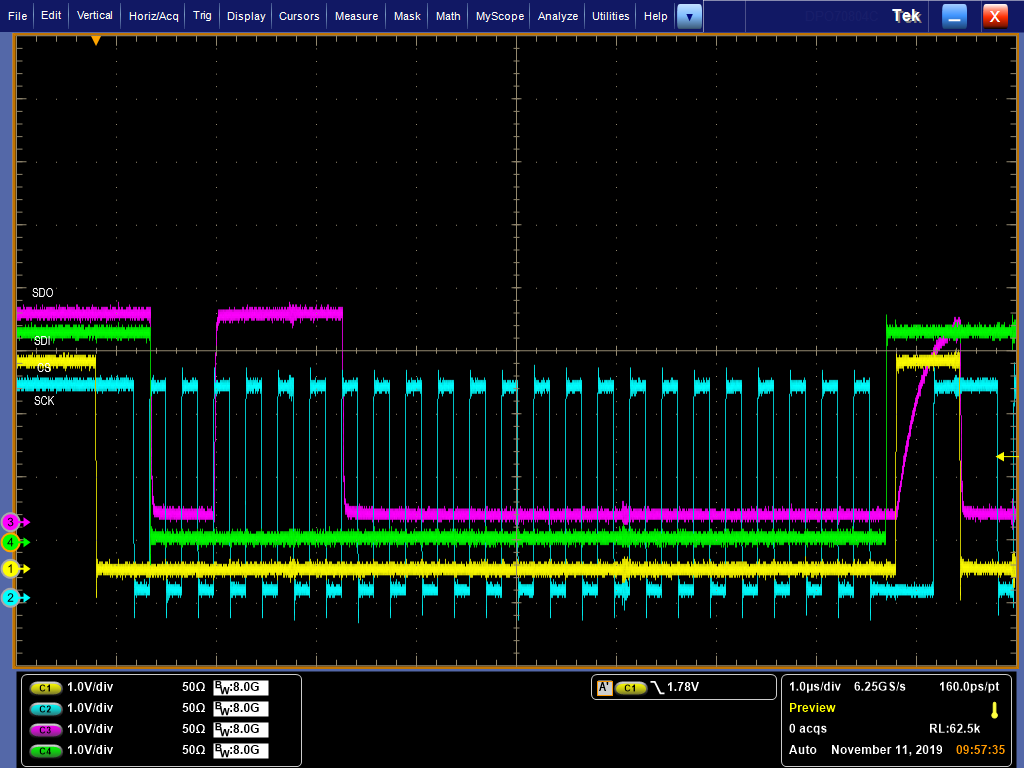
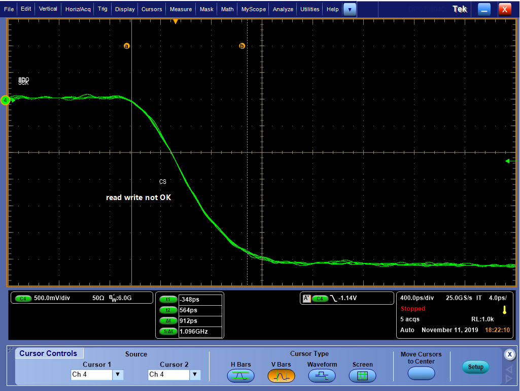
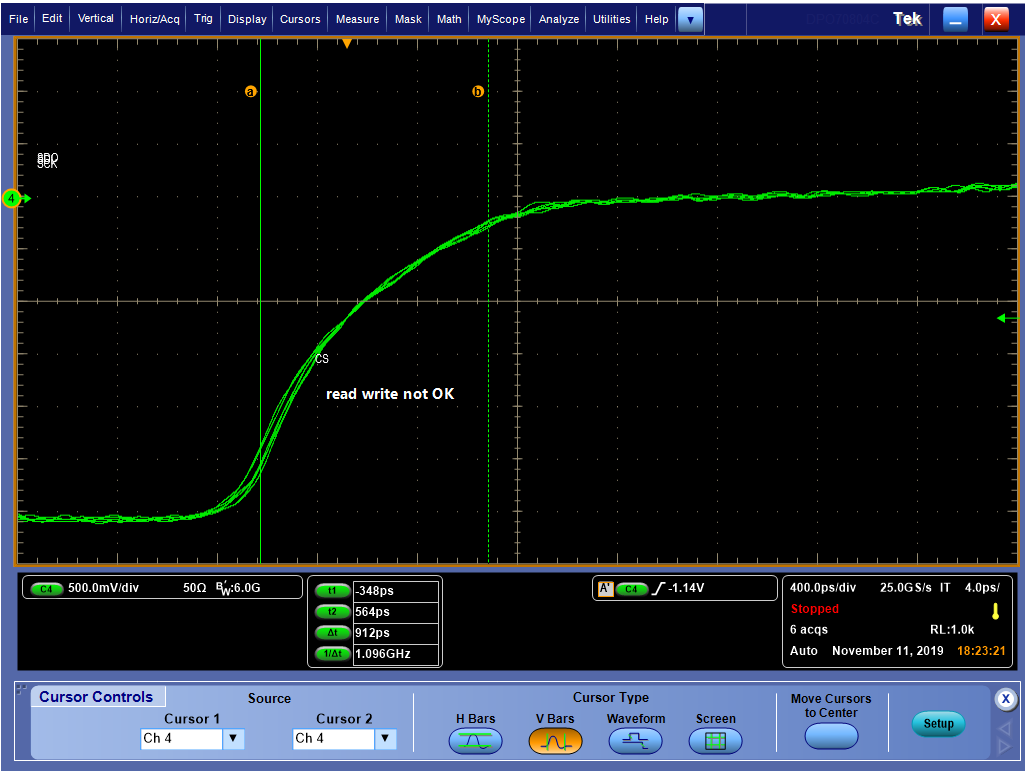
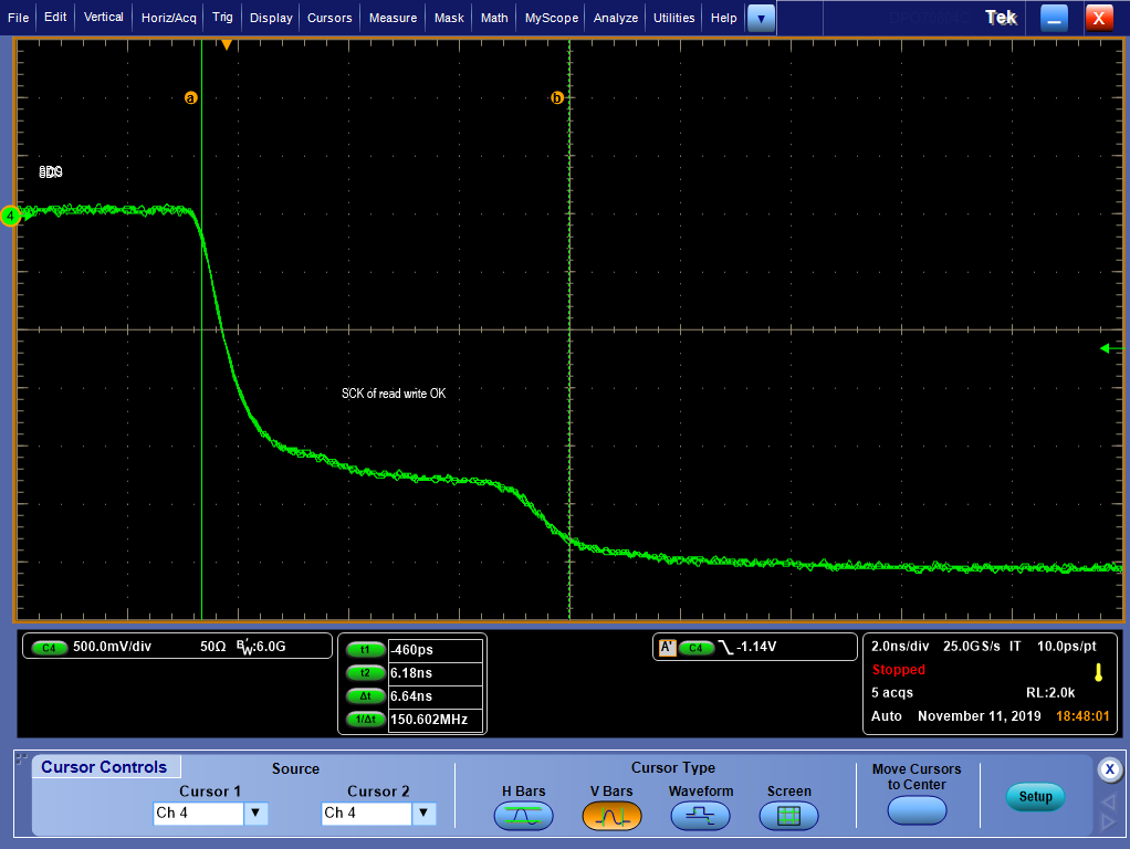
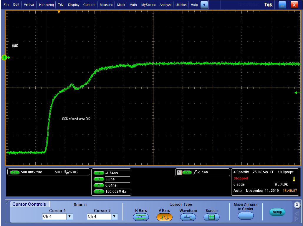
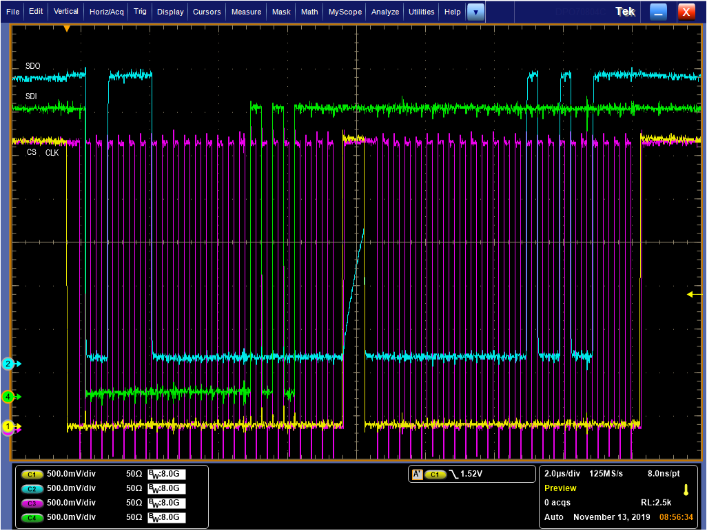
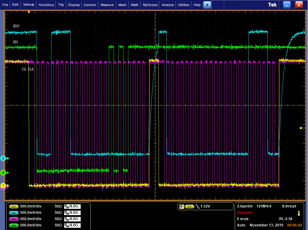
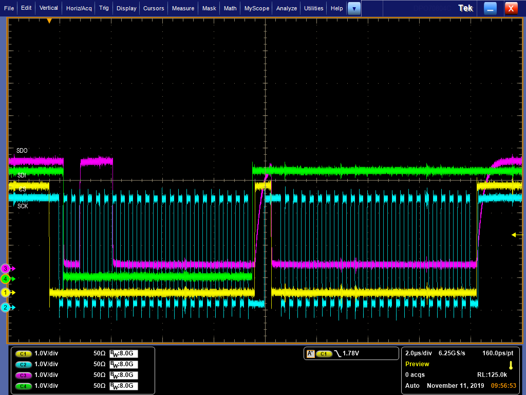
the FPGA SPI code should matter, bu I can't locate it, here is the full waveform of reading reg0:

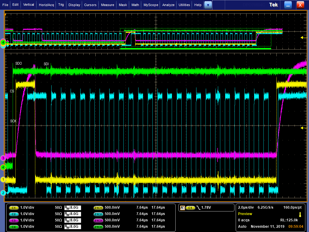
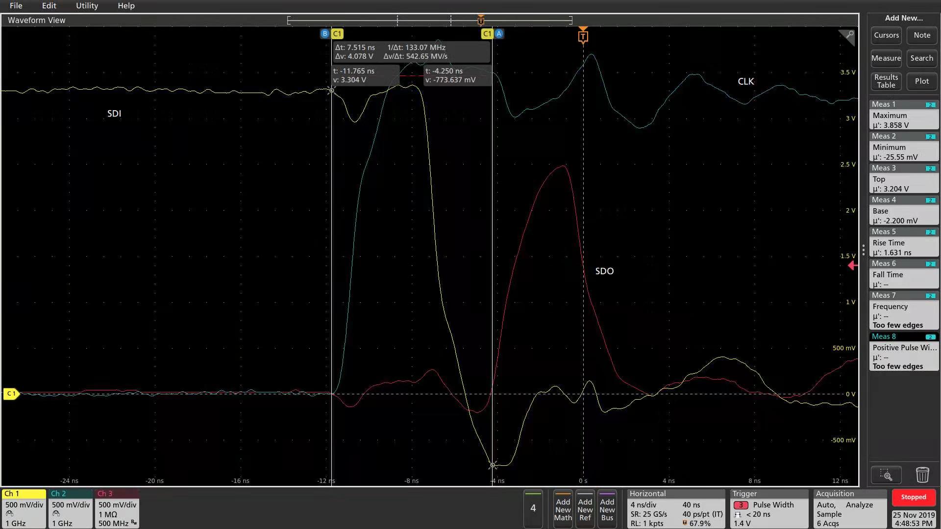
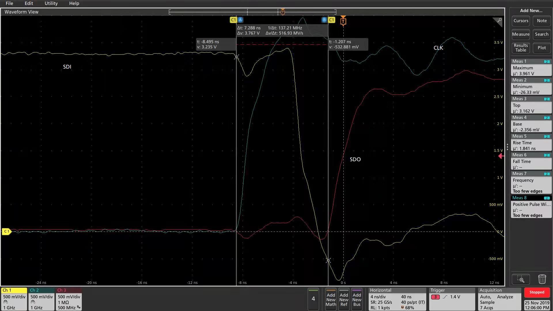
and the zoom in of waveform above:

  • I've captured the SCK and CS rising/falling edge waveforms below, all signals are tested very near to the chip's pin, the test probe is 6GHz bandwidth.

    I don't think the signals are poor quality.

  • Hello,

    Thank you for your query. I am going through your query. It looks like a timing issue. I will get back by tomorrow.

    Regards,

    Uttam Sahu

    Applications Engineer, Precision DAC

  • two experiments I added to debug it:

    1, add a 22pF capacitor between SCK and GND near the chip's IC, and the failed access becomes OK, then I remove the capacitor, it fails agian. I don't record the waveform.

    2, there's no reserved capacitor on my PCB board, so I try another similarly method, change the drive strength of the SCK in FPGA

    I have tried 4mA/8mA(default)/12mA, and only the 4mA are all good in my 5 test DAC8734 chips, in 8mA, the third chip access failed and the 12mA, the first failed. I've the SCK waveforms of 4mA:

    a poor signal quality leads to a successful access, so I feel so puzzled and helpless

  • thanks, looking forward to you!

  • sorry, this 4mA drive strength still has a problem, there's a phenomenon like this:

    SDI input:      1000,0000,0000,0000,0000,0000(0x800000)

    SDO output:  1000,0000,0000,0000,0011,1100(0x80003C)

    then:

    SDI input:      1000,0000,0000,0000,0000,0010(0x800002)

    SDO output:  0000,0000,0000,0000,0000,0110(0x000006)

    then:

    SDI input:      1000,0000,0000,0000,0000,0000(0x800000)

    SDO output:  1000,0000,0000,0000,0000,0100(0x800004)

    I repeat this and the conditions are the same.

    reset the DAC8734 the de-reset it, the phenomenon and the value returns doesn't change.

  • I find some contents on page 24 of  the datasheet confuse me:

    and the timing diagram of stand alone mode on page 11:

    1: which one is right?

    2: what's NOP Command?

  • Can anyone help me?

    I think the IC has a bug or some issues the datasheet not mentioned.

  • Hi,

    Sorry for replying late. Are you following the power supply sequencing as specified in Note (2) of page 2 and on page 22?

    Regards,

    Uttam

  • thank you, I've double checked the power sequence:

    5V(DVDD)→3.3V(IOVDD)→--17V(AVSS)→+17V(AVDD)→+6.5V(Vref)

  • Good. Have you also checked the gap between AVSS and AVDD during power-up as mentioned in Note (2) of the ABS max table?

    Regards,

    Uttam

  • Yes, AVSS ramps earlier than AVDD, it gets to -16V then the +17V(AVDD) starts up.

  • here is another waveform group:

    The data I send to two DAC8743 is 0x8000AF, 

    but  SDO returns are not the same, first is 0x00024F which is wrong and the second is 0x80003C which is right.

    the wrong IC and the right IC share the same power supplies on the PCB

  • I think the chip has a severe bug, if an SDI falling edge and a clock rising edge appear at the same time, an unexpected clock glitch may occur inside the chip.

    I hope TI can check it, after all, this chip was issued ten years ago and had never been updated since then.

    I have to consider aborting DAC8734 plan in the future disign.