This thread has been locked.

If you have a related question, please click the "Ask a related question" button in the top right corner. The newly created question will be automatically linked to this question.

ADS8695: ADS8695 meausre value is not fellow set value

Part Number: ADS8695

I used ADS8695 in my DAQ system. After my test, I found a problem: The ADC value is bigger than the set point value.

The test data is below:

Set value        ADC value        ADC value to calculation

0                         0                              0

4.183V               215072                     4.2V

3.684V               189440                     3.7V  

3.284V               168960                     3.3V

2.485 V              128024                     2.5V

The ADC configuration is:    Range = 1.25REF.

So according to the result is offest value: dV=16mV.  But I think the result is not meet the datasheet. Can you help me to check my design?

1、I check the ADC's ref voltage is OK;

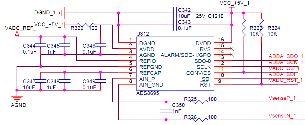
2、The schametic is bellow:

  • Hi Shengds,

    There are few issues or questions about your schematic:

    1. ADS8695 data sheet recommends minimum 4.7uF cap on REFIO shown in page 7 and Figure 53, however you are using (1+0.1)uF.

    2. Where is VsenseN_1 on input is connected to? is it connected to a ground or not?

    3. Is the Set Value measured result on ADC's input or just a set value on your DC signal generator?

    4. You are using splitted grounds (AGND_A and DGND_1), where are they connected on pcb board? ADS8695 data sheet recommends that using a single dedicated ground plan is strongly encouraged, which is shown in Layout Guideline section.

    Regards, 

    Dale

  • 2. Yes, VsenseN_1 is connetted to AGND.

    3. Set valude is on the ADC's input.

    4.AGND tight to DGND on the one point, I used a bead between the AGND and DGND. And my layout is two layer. Bottem layout is ground plant. And layout is different from the reference design from TI.

    I will check REFIO cap again.   

    I add offset in my software, and the test result is seen as OK until now.

    Thanks.

  • 1,I used external reference, the test result is same. so I think 4.7uF is not the cause of the problem !

  • Hi shengds,

    Even the capacitor on REFIO is not the concern in your current test, however the minimum capacitor should be always meet because that is the capacitor value we can guarantee the performance across the entire temperature not only at room temperature.

    ADS8695 is a 18-bit ADC. 2-layer pcb board may be okay for lower resolution ADC, but as a good rule of thumb, 4-layer circuit board should be used for data acquisition system with ≥16-bit ADCs, a single dedicated and solid ground plane is strongly recommended especially for ≥16-bit ADCs. Otherwise, you may see a lot of noise and offset. A splitted ground on 2-layer board may get a little bit better performance if the joint point is very close to the ADC on the pcb, however it will be very hard to achieve the performance specified in ADC datasheet.

    Regards,

    Dale

  • Hi Dale,

        Thank you for your advice. I will modify the layoout and REFIO cap to check the new design.