This thread has been locked.

If you have a related question, please click the "Ask a related question" button in the top right corner. The newly created question will be automatically linked to this question.

ADS1278EVM-PDK: ADS1278EVM-PDK

Part Number: ADS1278EVM-PDK
Other Parts Discussed in Thread: ADS1278, ADCPRO

Hi, am having ads1278-EVM kit with me. Running on a adopter with output 6V and capable of producing upto 2 Amps. I have installed all the software, able to load ADS1278 in ADC pro. 

I have given a input of 5Vpp with no offset. Now when i see it in ADCPRO multi channel scope with vref=2.5V it shows me correctly.

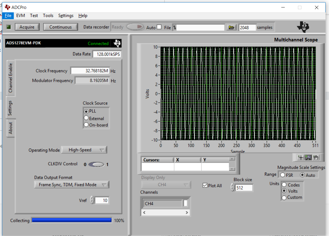
But when i change the Vref from the GUI as shown in image. The voltage shows in multi channel scope of ADCPRO is around +10 V to -10V. 

I am unable to understand its meaning?. What it shows can you explain me.

Also what is the max input i can give to my ADC Channel input when my REF+ is equal to 2.5 V and REF- is AGND?

  • Hello Navin,

    The reference voltage on the ADS1278EVM is fixed at 2.5V.  ADCPro just uses the value of Vref to calculate the input voltage from the sample codes.  This option is provided if you decide to use a different reference voltage, such as 2V.  This value should always be set to 2.5V for an unmodified EVM board.

    Channels 1-4 include an input driver amplifier.  With the on-board reference equal to 2.5V, the full scale input voltage on these channels  is +/-2.5V differential.  If the negative input is connected to ground, then the positive input can swing from +2.5V above ground to -2.5V below ground.

    Regards,
    Keith Nicholas
    Precision ADC Applications

  • Hi, What if I want to measure more than 3V on any of these channel. I mean Channel 1Positive is connected to 3.3V and channel 1Negative is connected to ground. Will I be able to measure 3.3V with providing 2.5V as refrence?

    Also at what maximum reference voltage I can provide to ADS1278?. Is it 3V ? and with this 3V refrence ,will I be able to measure a signal of 0 to 6V ?

    Because in the previous reply you mentioned that if I put 2.5V  as Vref, than I can swing my input voltage from -2.5V to +2.5V and not from 0 to 5V.

    That means in the datasheet of ADS1278, FSR is provided as 2*Vref, which made me assume that if I apply 2.5V as Vref, I would be able to provide a voltage of 0-5V as channel input.

  • Hi navin,

    Since your reference is 2.5V and Analog supply is 5V you can give the voltage in both positive and negative is 0 to 2.5V with Vcm = 1.25V. (=>Vcm=Vref/2)

    "Please note that the FSR is [AINP-AINN] = +/- 2.5V" And the reference voltage having a constraint with F_clock(see table 7 in datasheet)

    Theoretically your assumption for 3V ref and 6V supply is okay. But since the absolute maximum supply is 6V and it is not recommended, it is not good idea to implement. Instead you can feed the ratio of 3volt signal to input of ADC with proper Vcm, you will achieve the satisfied conversion. 

    Thanks and regards,

    Venkatesh P

  • Hi Navin,

    For clock frequencies equal or less than 32.768MHz, 2.5V is the typical value for the reference.

    Input channels 1 through 4 have an amplifier with a gain preset to 1.  If you do not need bipolar input levels, you can easily accommodate an input range of 0->5V by connecting ANNx to 2.5V and your input signal (0->5V) to the ANPx input.  

    In this configuration, 0V in will be interpreted as 0V-2.5V)=-2.5V and 5V input will be interpreted as 5V-2.5V=+2.5V.

    Regards,
    Keith