


Hello,
I have been trying to read values from the ADS7961 using STM32f07 using SPI but all I am getting is garbage values on the SPI Receive register of the Microcontroller.
it could be because I am packing the data wrongly while sending on the SPI.
I am trying to read the data from the 2nd channel for starters and thus sending 0x1100 i.e. manual mode and address of the second channel.

the yellow one is the clock and the blue one is the microcontroller output (MOSI) (the data capture is of the 3rd frame)
the response of the above frame is attached below
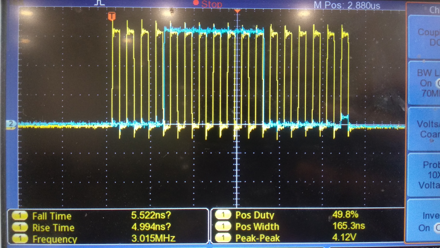
the Yellow one being the clock and the blue one is the ADS output (MISO) (the data capture is of the 3rd frame)
as you can see the data received should contain the channel number i.e. 2 (according to the configuration sent) but it does not do as it supposed to do.
I believe the frame transmitted is correct and the code is also mentioned below. but I am missing out something.
//////////////////////////////////////////////////////////////////////////////////////////////////////////////////////////////////////////////////////////////////////////////////////////////////////////////////////////////////////////////////////////////////////////////////////////////////
void ManualModeTest()
{
	uint8_t channel = 2;
	uint8_t dataTx[2] = {0}, dataTxSend[2] = {0}, dataRx[2] = {0};
	uint16_t tempDataTx = TransPack(channel);
	memcpy(dataTx, &tempDataTx, sizeof(tempDataTx));
	fliparr(dataTx, dataTxSend, 2);
	ADS_TransmitReceiveFrame(dataTxSend, dataRx, 2, HAL_MAX_DELAY); //dataRx is the received data, 2 is the size, HAL_MAX_DELAY is the timeout
}

void fliparr(uint8_t *arr1, uint8_t *arr2, uint8_t size)
{
	for(int i = 0 ; i<size; i++)
	{
		arr2[(size-1) - i] = arr1[i];
	}
}

uint16_t TransPack(int channel) {
    uint8_t mode = 1;
    uint8_t gpioProg = 0;
    uint8_t Ref = 0;
    uint8_t power = 0;
    uint8_t GPIO = 0;
    uint8_t dioOut = 0;

    uint16_t transPack = mode;				//4 bits
    transPack = transPack << 1;
    transPack = transPack | gpioProg;		//1 bit
    transPack = transPack << 4;
    transPack = transPack | Ref;		       //4 bits
    transPack = transPack << 1;
    transPack = transPack | Ref ;		       //1 bit
    transPack = transPack << 1;
    transPack = transPack | power ;	              //1 bit
    transPack = transPack << 1;
    transPack = transPack | GPIO;	              //1 bit
    transPack = transPack << 4;
    transPack = transPack | dioOut;		      //4 bits

    return transPack;
}
//////////////////////////////////////////////////////////////////////////////////////////////////////////////////////////////////////////////////////////////////////////////////////////////////////////////////////////////////////////////////////////////////////////////////////////////////
the SPI settings are as follows :
hspi1.Instance = SPI1;
hspi1.Init.Mode = SPI_MODE_MASTER;
hspi1.Init.Direction = SPI_DIRECTION_2LINES;
hspi1.Init.DataSize = SPI_DATASIZE_8BIT;
hspi1.Init.CLKPolarity = SPI_POLARITY_LOW;
hspi1.Init.CLKPhase = SPI_PHASE_1EDGE;
hspi1.Init.NSS = SPI_NSS_SOFT;
hspi1.Init.BaudRatePrescaler = SPI_BAUDRATEPRESCALER_16;
hspi1.Init.FirstBit = SPI_FIRSTBIT_MSB;
hspi1.Init.TIMode = SPI_TIMODE_ENABLE;
hspi1.Init.CRCCalculation = SPI_CRCCALCULATION_DISABLE;
hspi1.Init.CRCPolynomial = 7;
hspi1.Init.CRCLength = SPI_CRC_LENGTH_DATASIZE;
hspi1.Init.NSSPMode = SPI_NSS_PULSE_DISABLE;
//////////////////////////////////////////////////////////////////////////////////////////////////////////////////////////////////////////////////////////////////////////////////////////////////////////
Any help would be really appreciable.
Thanks in advance.
Pranay
