This thread has been locked.

If you have a related question, please click the "Ask a related question" button in the top right corner. The newly created question will be automatically linked to this question.

SM73201: Problem to read ADC by using Arduino

Part Number: SM73201

Hi,

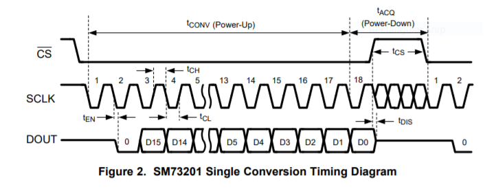
I am trying to read  ADC SM 73201 by using Arduino. As per datasheet it is 2'S complement biniary out could you please give me some hints how I can read the adc value and convert into voltage. My reference voltage is 2.048.

thanks

Ahmed

  • Hi Ahmed,

    Welcome to the TI E2E Community.

    First, since you are using a 2.048V reference, the full scale input range will be from -2.048V to +2.048V differential.  If you connect the inputs per Figure 30 in the datasheet for a single-ended input, and set the negative input (pin 3) to 2.048V, then with the positive input (pin 2) at 0V, the differential voltage seen by the ADC will read -2.048V, or negative full scale.  With the positive input at 4.096V, the differential voltage seen by the ADC will read +2.048V, or positive full scale.

    For the SPI communication, you need to pull /CS low using an IO pin (SCLK should be high when /CS is pulled low), and then provide 18 SCLK's to get the full 16b conversion result.  The first two bits are discarded, and the MSB (the sign bit for the 2's complement reading) will then launch on the 3rd SCLK falling edge and can be captured by your host MCU on the 3rd SCLK rising edge.

    Once you have acquired the 16b signed integer (CODE), with a decimal range of -32768 to +32767, you can then calculate the input voltage as follows:

    Vinput = CODE/32768*Vref

    For a decimal code of 10,000, the input voltage would be Vinput=10000/32768*2.048V=+0.625V.  The actual voltages on the ADC inputs when measured relative to ground would be -IN=+2.048V and +IN= +2.673V.

    Regards,
    Keith Nicholas
    Precision ADC Applications

  • Hi Nicholas,

    Thanks for the detail answer. I will try with your instruction and come to you with my code.

    regards

    Ahmed

  • Hi Nicholas,

    Please see my code below but I didn't see any thing on serial port. I am using Arduino Micro 32U4 controller. Actuall I would like to read 0 to 1mv signal with 30uV step size. I have done my hardware part and trying to read by using programming. for next I will use Multiplexer 74HC154 for CS and read 12 differnt ADC by using single Arduino. Need your help in this regards and also guide me how I creat single/two clock pulse delay as you descibed previous for reading ADC.

    Ahmed

    #include <SPI.h>

    /* SPI Pins used:
      MISO = 11
      SCK = 9
      CS = 27
      */


    const int CS = 27; //Chip select output. Controls the slave device

    int adcValue=0;//This is the value in the ADC output register
    byte dummyByte;//Byte that does nothing but allows the conversion cycle to complete.
    byte upperByte;//Most significant BIT
    byte lowerByte;//Least significant BIT


    void setup(){
     SPI.begin();//Enables the SPI interface
     SPI.setDataMode(SPI_MODE0);
      pinMode(adcCS, OUTPUT);

       Serial.begin(9600);

     
    //Reset cycle for the ADC. Initializes the chip on power up. Occurs only 1 time.  
    digitalWrite (CS, LOW);
    dummyByte = SPI.transfer(0); // Initialization/Reset clocks
    digitalWrite (CS,  HIGH);
     
    }
     
     void loop(){
       // read out data from prior conversion, provide clocks for next conversion

    digitalWrite (CS, LOW); //Enables SPI
    upperByte = SPI.transfer(0);  // read one byte of result back
    lowerByte = SPI.transfer(0);  // read one byte of result back
    dummyByte = SPI.transfer(0); // finish providing 18 clocks to complete conversion
    digitalWrite (CS,  HIGH); //Disables SPI
    adcValue = (upperByte<<8) + lowerByte; // Moves the upperByte to the left, then adds
                                     //the lowerByte.  Combining the two equals the adcValue.


    Serial.println(adcValue, DEC);//Prints the ADC Value to Serial port.
    float voltage = adcvalue * (2.048 / 65535.0);
    Serial.println(voltage);//Prints the ADC Value to Serial port.
                                     

       delay(250);
    }
  • Hello Ahmed,

    I am not proficient using the Arduino , but if I follow your above code, then you need to modify as follows.

    The 6 MSB's of the result will be in the UpperByte, the next 8 bits in the lowerByte, and the 2 LSB's in the dummyByte.

    For the UpperByte, you need to shift left by 10, not 8.  The lowerByte will require a shift left of 2, and the dummyByte will need to Shift Right 6.  You would then combine (OR) all three values to get the final result.  If adcValue is a 32b integer, you will want to force the upper 16b's to 0 since the first bit output by the ADC is floating and could randomly read back as a 0 or 1.


    Regards,

    Keith