This thread has been locked.

If you have a related question, please click the "Ask a related question" button in the top right corner. The newly created question will be automatically linked to this question.

ADS1118EVM: ADS1118EVM returns railed data. Configuration Correct?

Part Number: ADS1118EVM
Other Parts Discussed in Thread: ADS1118, HDC2080

Hi,

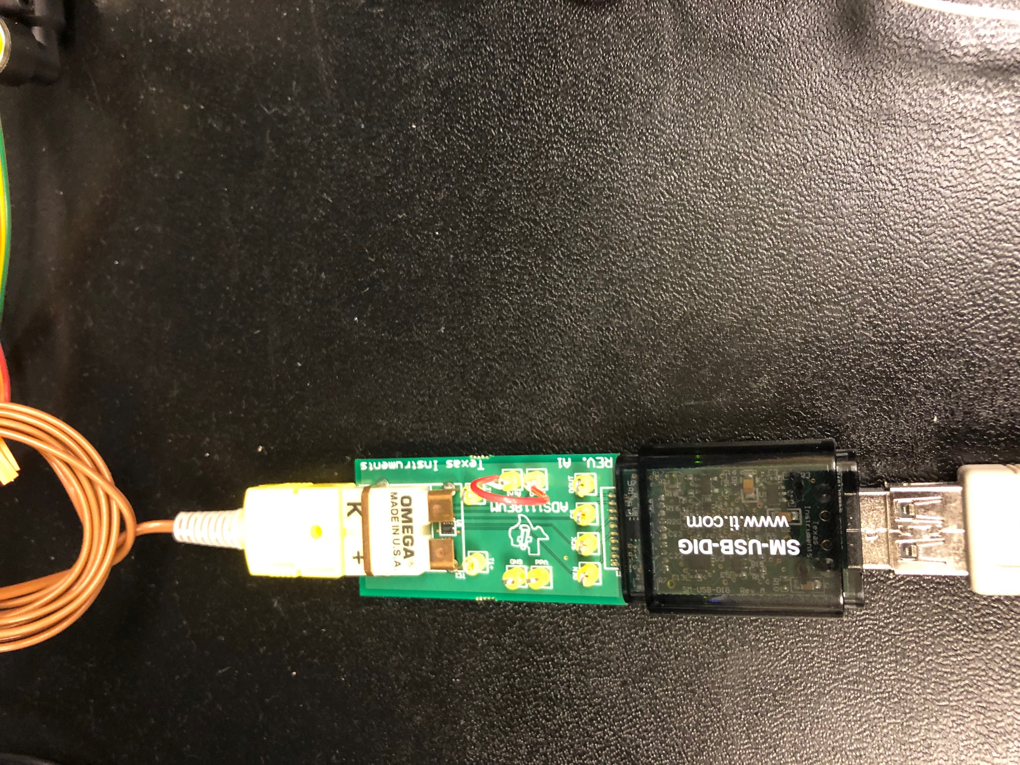
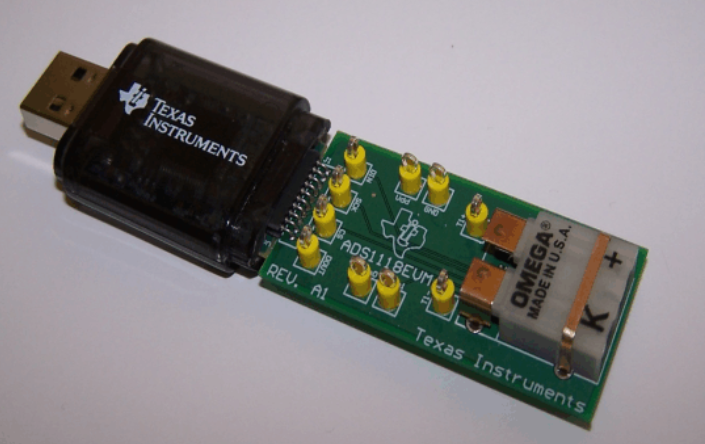
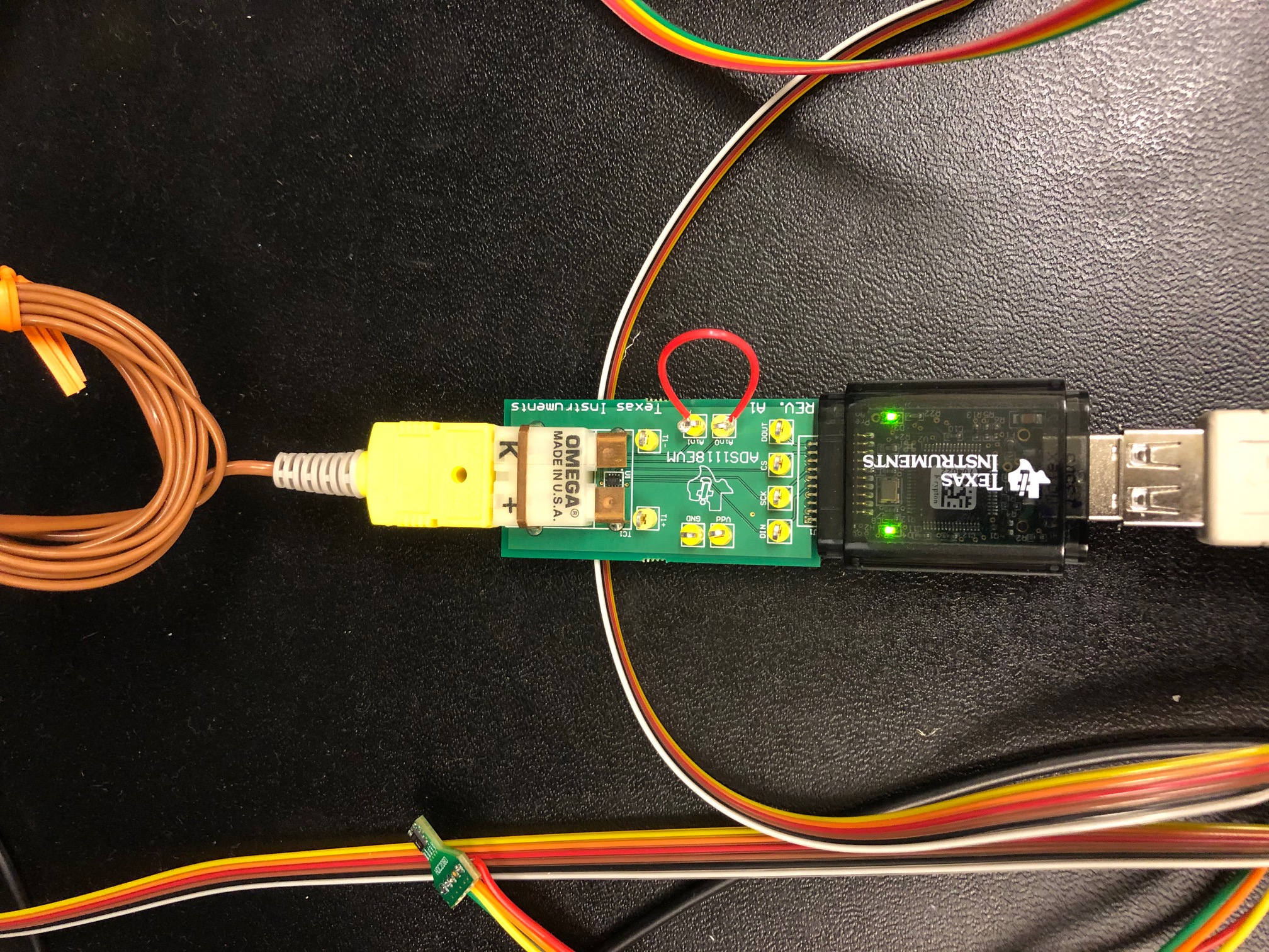
I have the ADS1118EVM and it is hooked up to the USB dongle and has a K type sensor attached (the sensor that came with the EVM).  The data coming back seems to be railed.  Guessing that either my configuration is not quite correct or I'm having some other hardware issue.  Please help.  I've tried various configuration settings and they all return railed data.

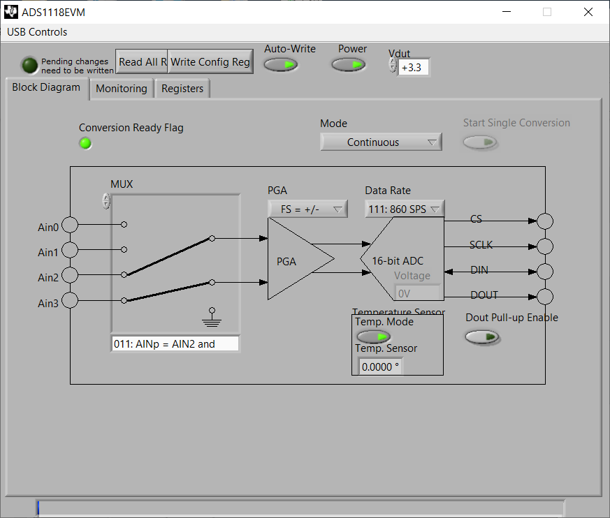
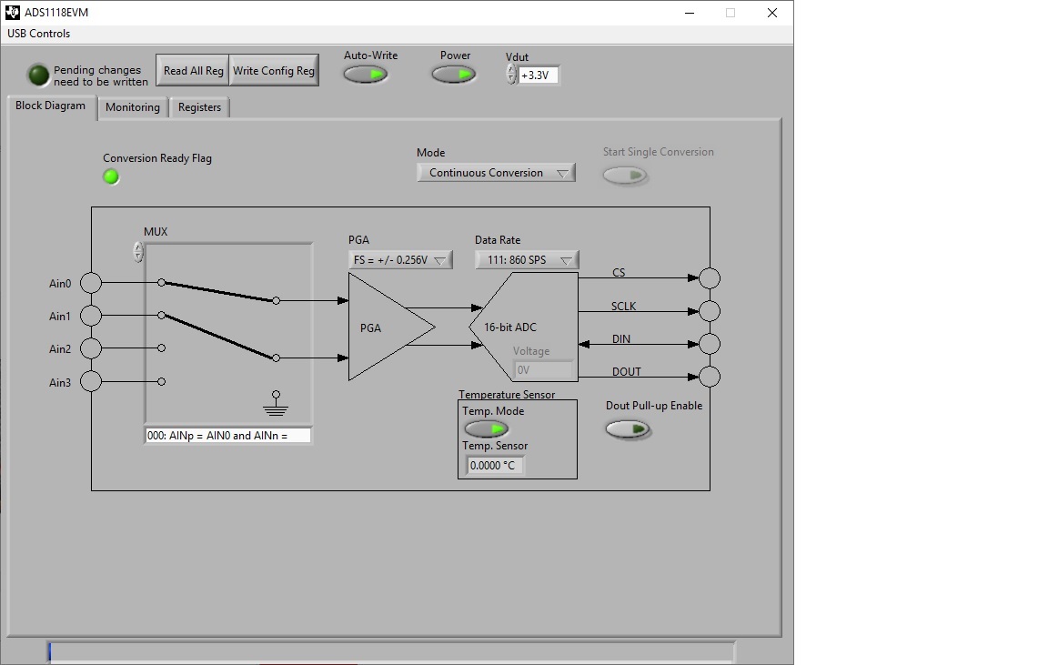
I have it configured as such:

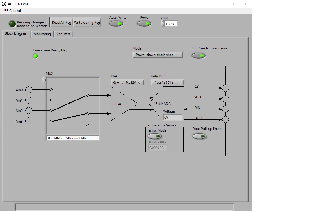
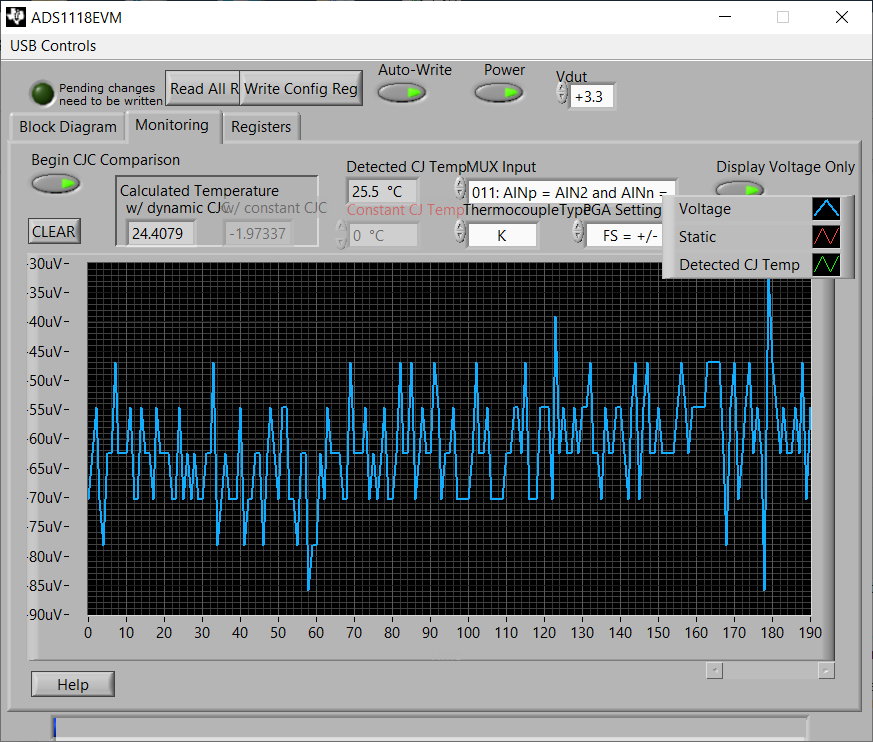
However, the data coming out seems to be railed.

Here are the registers:

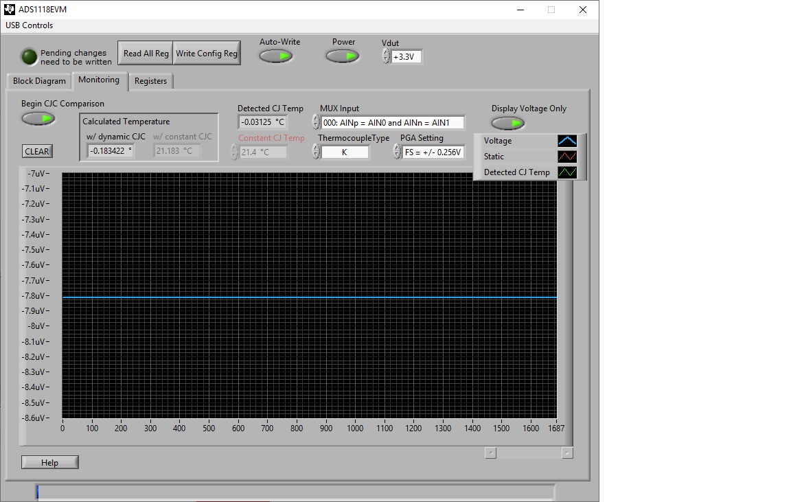
Conversion register is always railed?

  • Jim,

    I'd admit the ADS1118EVM GUI isn't the easiest to use, but there are a couple of things to try. 

    First, I would check to see if the device is converting at all. Set the input mux to AIN0/AIN1 and short the inputs together at the test loops on the board using a wire. I would then set the PGA to the smallest range (±0.256V). Then enable the Temp Sensor (button below the ADC on in the Block Diagram tab). I would also put the device in Continuous Conversion Mode (above the ADC/Data Rate tab). Then Write the Config Reg (or use the Auto Write button). Set the data rate to 860SPS. With this EVM, conversions will alternate between the ADC input and the internal temp sensor.

    The start the Begin CJC Comparison. If the temp sensor is enabled, then you should see the Detected CJ Temp value a little (you may need to blow on the board or even touch the board to warm it up a little. If the Detected CJ Temp value does vary, then the ADC is doing a conversion.

    If you want you can look at the Display Voltage Only, so you can see the value being read by the ADC. With the inputs shorted, you may see 0V, but it's likely that you'll have some small amount of offset, and there may be some small amount of noise because the data rate is at maximum. If this voltage also moving, then the ADC is converting at least on the AIN0/AIN1 channel.

    After that you should be able to see if the thermocouple is actually working and verify that the AIN2/AIN3 inputs are correctly converting. To be honest, the registers tab was not correctly displaying for me either. However, I was able to get some readout from the ADC.

    You can also verify the test points for T1+ and T1-. They should connect to AIN2 and AIN3.

    Joseph Wu

  • Joseph,  Thank you for getting back to me.

    I jumped the loopback from Ai0 and Ai1 as shown.

    Configured the ADS1118 as you initially described.

    Checked the Output and didn't see any activity by blowing on it or even holding it in my hand.

    No variation at all.  :-(

    ?

  • Jim,

    I think the SM-USB-DIG is upside down. I believe that the TI logo should be on the top:

    In your picture, you have the SM-USB-DIG and the website text on the top. The SM-USB-DIG connector isn't keyed and could be connected backward.

    Joseph Wu

  • Joseph,

    You are correct.  Initially I had it right but somewhere along the line it got flipped in error when I disconnected to put on the loopback.  Question is, since I connected it wrong, can the device survive that event?  Even with it hooked up correctly this time, it doesn't appear to be changing voltages.

    Same Setup.

    Output still didn't seem to vary voltages by holding or blowing on the sensor.

    And the Config Register.

  • Jim,

    I think your pins are still misaligned. It looks like the pins from the SM-USB-DIG are shifted off by one pin from the connection to the ADS1118EVM. Again, the SM-USB-DIG case opening is much larger than the pin connectors.

    This is from the photo you sent me. The top red line shows pin 1 of the SM-USB-DIG connecting to pin 2 of the ADS1118EVM.

    Joseph Wu

  • Ah, yes.  I saw that, unplugged, and aligned them.  thanks. 

    So it looks like good data coming through now.  See captures below.  You can see where I held the thermocouple and then let it go.  Next step is to read the device through an Aardvark I2C_SPI adapter.  I can read your TI HDC2080 through the Aardvark I2C no problem.   I have a couple questions regarding SPI, so I'll be creating a new request so we can close this one out.  Thank you Sir.

  • Jim,

    No problem. I'm glad you got it working. I'm also glad that you sent the photo that was clear enough to see the misalignment. Without that, we might still be scratching our heads.

    When you come up with other questions for the device, feel free to post back.

    Joseph Wu