This thread has been locked.

If you have a related question, please click the "Ask a related question" button in the top right corner. The newly created question will be automatically linked to this question.

ADS1235EVM: load cell EVM setup

Part Number: ADS1235EVM
Other Parts Discussed in Thread: ADS1235

I currently have a load cell hooked up to the ADS1235EVM, but I am not being able to collect any readings from it. I would appreciate any tips on how to make this work.

Here is a picture of the hardware setup:

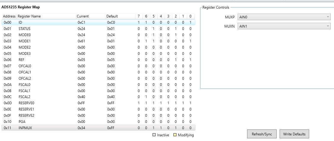
This is the configuration of the registers:

And this is the result I am getting:

I'm sure to be missing something simple - any help is appreciated!

Thank you!

  • Hi Lenio,

    Looking at your register settings and the EVM picture, it looks like you are intending to use the ADS1235 EVM's bridge driver to power the load cell via the J5 header. If you want to use the bridge driver to power the load cell or perform bridge chopping, you need to enable the GPIO pins via the MODE2 register. The default bridge driver configuration uses ACX1 and ACX2 on this EVM, which are GPIO2 and GPIO3 on AIN2 and AIN3 on the ADS1235, respectively. This would require you to set MODE2[7:6] = 11b. You would then need to control the GPIO logic level via the MODE3 register, specifically bits 2 and 3. This will allow you to change the polarity of the bridge excitation voltage. As it stands right now, both inputs to the bridge driver are pulled low, so there should not be any output voltage on EXC+_OUT or EXC-_OUT. This would explain the bad data you are seeing.

    If you want to bypass the bridge driver and power the bridge directly without the benefit of chopping, AVDD and AVSS are accessible on the board directly to the left of J5 in the picture from your original post. Note that the headers are not supplied on this board however, so you would have to add them manually.

    -Bryan

  • I appreciate the thorough and concise reply - everything is working now. Thank you!