This thread has been locked.

If you have a related question, please click the "Ask a related question" button in the top right corner. The newly created question will be automatically linked to this question.

DAC7750EVM: Help to config output current

Part Number: DAC7750EVM
Other Parts Discussed in Thread: DAC7750, DAC8750

Hi,

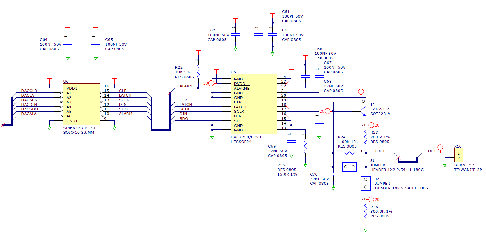
We're using DAC7750 at PCB DAC7750EVM - http://www.ti.com/lit/ug/sbau205a/sbau205a.pdf.


First test we are using the EVM software. We just config the output range to 4-20mA and enable the output.

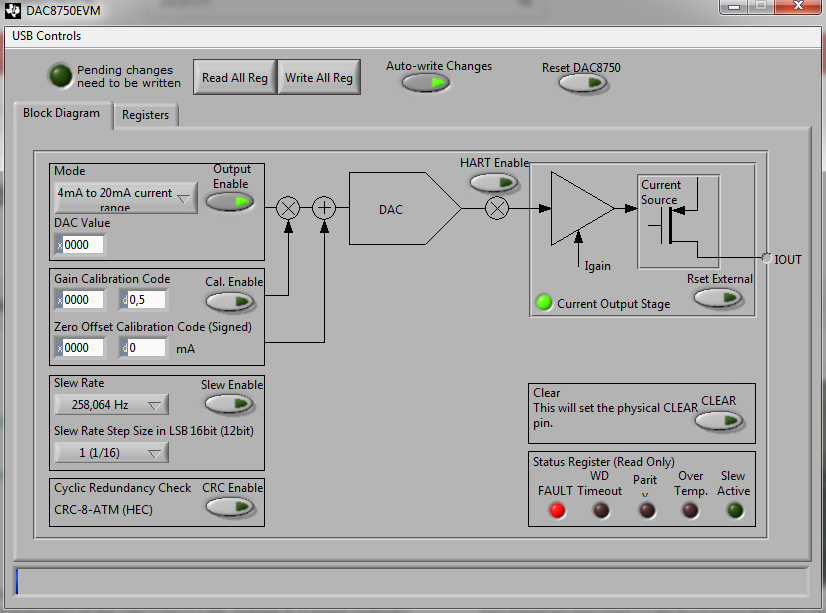
Acording to DAC7750EVM document, section 3.6.7, we need measure the drop voltage on R4 of 300ohms. The JP6 must be connect. 

After enable the "Output Enable" button, we get a FAULT (bit 2 - Iout fault) on status register.
The drop voltage of R4 is 1.13V, the 4mA that was select. Power supply is 22.5V.
Whatever I write on DAC Register, the current output not change.
The FAULT ALARM goes to zero after reset or disable the Output Enable bit.


Please, what am I doing wrong?

Thank you!

  • Hello Uilter,

    To figure out the issue, I'd first like to confirm that the EVM board is connected and configured correctly.

    1. What is the AVDD supply current after power up before writing any commands? It should be 2-4 mA depending on the source for the DVDD supply.

    2. Is JP3 installed? If installed, then an external DVDD needs to be provided at J1 or JP9 needs to be installed. If JP3 is not installed, then JP9 should be uninstalled as well and no power should be provided at J1. 

    3. Confirm REFOUT=5V by measuring pin 6 of JP4.  Confirm REFIN=5V by measuring pin 1 of JP4.

    If all above looks good, connect JP6 and retry the test and it should work. 

    Let me know your findings.

    Regards,

    Reza

  • Hi Reza,

    Thanks for your reply and questions.

    1. The power supply is regulated to 22VDC and the consumption is 12mA. It's not look good, right?
    2. JP3 is not installed. The 5V on DVDD is provided by DAC7750.
    3. REFOUT and REFINT with 5V.

    Just a double check, the test is just put an amperemeter on J5. Am I right?

    Thanks!

  • Uilter,

    Is the 12mA current used up by the EVM board only? If that is the case, then there is an issue with the setup and that needs to be resolved first.

    Is J9 installed on the board? It shouldn't be installed if DVDD is provided by the DAC7750. Also can you confirm that the 2 LEDs on the SM-DIG are lighted up and facing upwards in your setup?

    Please provide a picture of your  EVM board including the SM-DIG if you can. 

    Regards,

    Reza

  • Reza,

    J9 is not installed on the board. The 5V is present on DVDD pin.

    About the communication, I put a logic analyzer and I'm able to see the data on the bus.

    About the picture, I made a mistake.
    The circuit is equal to EVM board, because of it I mentioned on this post.


    Here is the schematic:
    J1 is not mounted and J2 is mounted to measure current.
    U6 is not mounted. I put here the SM-DIG to test.


  • Uilter,

    Did you confirm if the 12mA AVDD current is all flowing into the DAC7750 chip or is it shared with other devices in the design? If it is all flowing into AVDD pin of the DAC8750, then that issue has to be figured out first.

    The schematic diagram looks fine. Can you try writing and reading back the control register addr 0x55 to confirm correct SPI communication? If the SPI is fine, can you retest your board with jumper J1 connected? This would bypass the external FET and drive IOUT pin using the internal FET. 

    Finally, can you provide the voltage levels of the all supplies you have for the U5 & U6? Thanks.

    Regards,

    Reza

  • Reza,

    Yes,  I confirmed the 12mA on DAC7750.
    This circuit is entirely isolated by the rest of the board.

    SPI it's fine and I double check with the logic analyzer on it.

    The voltage level on U5 AVDD pin is 22V (on my test) and U6 we power with 5V from DVDD of DAC7750. (non-isolated side)
    The isolated side, connected to MCU, we use 5V either. Note on this test the U6 is not mounted.

    I connected the J1 and retest as you ask. The current on Iout go to 92mA. =/

    Tomorrow I will get a new DAC7750 and replace it. I let you know the results.

    Thanks.

  • Thanks for the update Uilter. I'll be waiting for your results after replacing the part. 

    Thanks.

  • Hi Reza,

    We replaced the DAC7750. It works right now. =)

    Thank you for your support.

  • Great! Can you close out this post thread? Thanks.

    Regards,

    Reza