This thread has been locked.

If you have a related question, please click the "Ask a related question" button in the top right corner. The newly created question will be automatically linked to this question.

AFE4403: Questions about AFE4403 register parameter configuration and ADC output

Part Number: AFE4403

Hi Team,

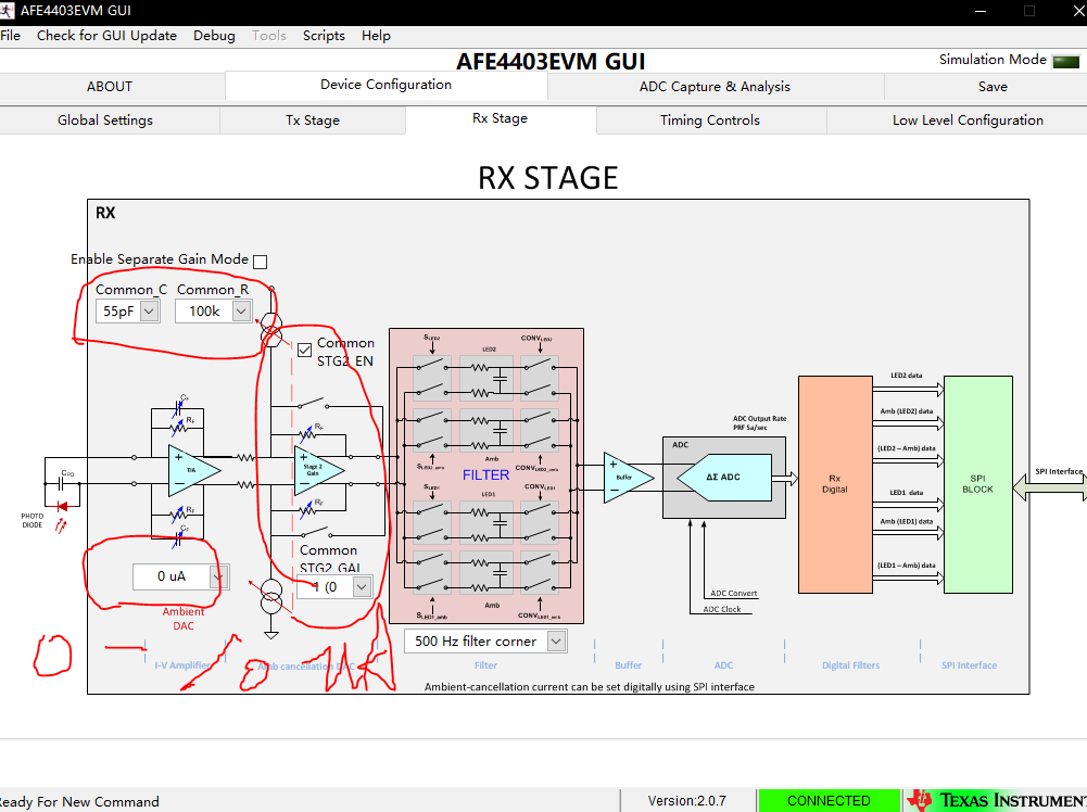
Customer used AFE4403 and SFH7050 to collect pulse wave signals. He encountered some problems while setting the register parameters. Regarding the parameter Ambient-cancellation current, his understanding is the ambient light cancellation current, which can be set by SPI, the range is 0 ~ 10uA.

Question:
1. How does this adjustment affect pulse wave acquisition?
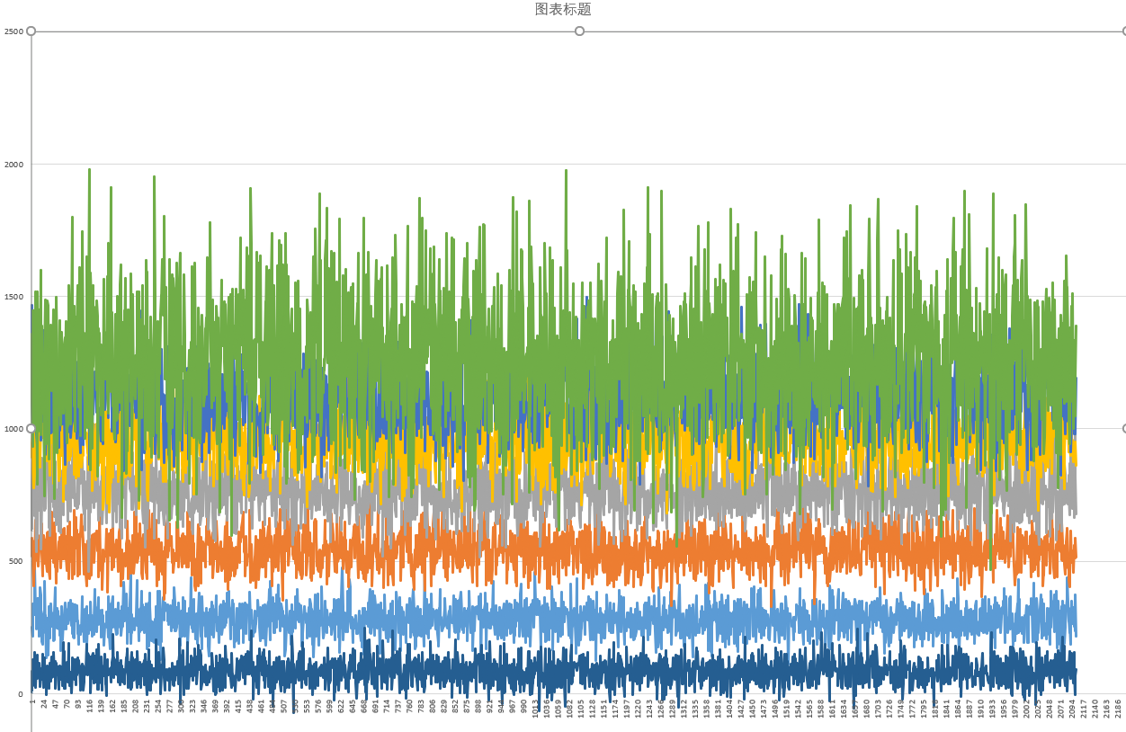
2. Adjust from 0 to 10uA from large to small. How does this change the voltage collected by the ADC? He emphasized the SFH7050 light to the minimum. He covered the photosensitive part of the front side silicon photocell with black tape. He set the cancellation current to 0-10uA. And he found that the ADC output is as shown at 0-6uA, and the output is all zero at 7-10uA.

  • Thank you for your translation and transmission。The interface settings of   AFE4403EVM GUI   are as shown in the figure。AFE4403 EVM board uses the SFH7050 as its driving light source。

    When I simulate the green light to the weakest (LED 2 / LED 3 Current = 0), and cover the SHF7050 with a black opaque material, the output value of the ADC is gradually increasing when the figure is 0-6uA. Voltage, but the ADC output will all become 0 at 7-10uA. So I want to figure out what current does Icancel compensate for when I set the normal light intensity? In addition to the PPG signal reflected by the skin, the light reflected by the shell and other light in the environment were measured, which of these were offset by Icancel?