Hi team,
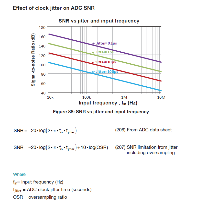
Why the clock jitter will affect the SNR of ADC? How to get the following equation?
This thread has been locked.
If you have a related question, please click the "Ask a related question" button in the top right corner. The newly created question will be automatically linked to this question.
Hi Charles,
Remember the clock determines when the input signal is sampled. If we suppose we had a perfectly periodic clock and input sine wave, then we would expect that input sine wave to be sampled at the exact same points every cycle. If we introduce some variation in the period of the sampling clock though, sometimes we may catch the sine wave at a slightly lower value than before and other times slightly higher. Since the time at which we sample the waveform changes randomly and the sine wave is constantly changing in time as well, this looks like noise in our data converter output.
It may be easier to understand the SNR equation by setting it up as a ratio. Tjitter is 1/fjitter. 2*pi*fin is the rate of change of a sine wave (signal), and this is divided by the error in that rate of change caused by sampling the signal at a different point (noise). If your fjitter was 0Hz (perfect clock), then SNR would be infinite (there are of course other factors that limit ADC SNR).
I hope this helps!
Best,
Zak
Hi Zak,
Good day to you!
Thanks for your answer. And then, How do I get 10log(OSR) in equation 2?
Hi Charles,
The second term is term is commonly known as the process gain. The minimum requirement to accurately represent a signal is to sample at the nyquist frequency, which is twice the bandwidth of your fastest signal (some applications don't actually follow this and will sample below the nyquist rate and rely on the aliased signal, but this is rare and usually only done for high speed applications). The oversampling ratio is how many times greater than the nyquist rate you sample your signal. Sampling faster allows you to push the quantization noise of an ADC out to higher frequencies, and then you can filter to your desired sampling rate and eliminate much of this noise in the band of interest. This is how a delta-sigma converter operates. The filter basically acts as an averaging function. If you have uncorrelated noise sources, then noise will reduce by the square root of the number of samples you use to represent a value. So taking 4 samples will reduce noise by a factor of 2, or yield a 6dB improvement in SNR. Notice, 10*log(4) is also 6dB. This is one way you can improve the SNR of a system! This is why when you look at an FFT the noise floor can be so much lower than the theoretical noise floor of the data converter you are measuring. The process gain from using a large number of samples in an FFT allows you to lower the measurement noise floor and gives you better resolution.
Best,
Zak