This thread has been locked.

If you have a related question, please click the "Ask a related question" button in the top right corner. The newly created question will be automatically linked to this question.

ADS1014: PT100 Wheatstone bridge

Part Number: ADS1014
Other Parts Discussed in Thread: ADS112C04

Hello,

I want to implement a circuit to measure temperature using a 2-wire PT100 RTD (temp. coefficient 0.385 Ohm/°C).

The RTD element is positioned very close to the rest of the circuit, about 15 cm.

The goal is to measure temperature in the range (10°C : 50°C) with a resolution of 1°C, minimizing the hardware cost.

I know that the best approach would be to bias the RTD with precise current generator, but since the required temperature resoution is not so precise I was thinking of using a simple Wheatstone bridge circuit followed by ADS1014 ADC.

I attach the sketch of the circuit.

For the given temperature range and circuit elements I made these calculations:

  • RTD range (103.85 Ohm : 119.25 Ohm)
  • Vdiff range (2.4 mV : 12 mV)
  • Vcm 65 mV

I would set the ADC's FSR to be +-256mV, so LSB= 0.125mV which corresponds to about 0.5°C; the full Vdiff range would cover about 80 ADC levels.

My questions are the following:

1) The common mode voltage is close to ground: is this a problem for the ADC?

2) I drew a low pass filter between the bridge and the ADC input, with the purpose of avoiding aliasing. Is this filtering approach correct? How should I size the components Ra, Rb, Cdiff, Ccm?

3) Is this circuit able to guarantee a temperature resolution of 1°C?

Thanks,

Riccardo

  • Riccardo,

    This question requires a bit of analysis, but I'll just answer the questions in the order they're asked.

    1. No, the common-mode voltage is not a problem for the ADC. The absolute inputs for the ADC range from GND to VDD. Any voltage within the supply should be ok as long as the measurement is within the full-scale range.

    2. This type of RC differential and common-mode filtering is common for differential ADC measurements. For this device, I would start with 1kΩ series resistance and then select a differential bandwidth that is about 10x of the data rate. Then select a common-mode bandwidth of 20x of the differential bandwidth.

    3. I'm unsure if this would guarantee accuracy, but it depends on what variables you are able to control. Let's just do some basic analysis to show what I mean. First, the ADS1014 has an LSB size of 125uV in the smallest FSR setting. The typical offset is probably about 25uV. You could probably use 5x of this for a max (which would be about 1LSB for this FSR setting). For the RTD measurement, if you calculate the output of the bridge, you get a voltage of 245uV/°C. That means each °C will be resolved by less than two LSBs. There will be errors from the bridge that you construct based on the tolderance of the resistors. If you assume 0.1% resistors, a single resistor error would be about 64uV of error, which would be about half an LSB.

    Additionally, there would be error from the RTD itself depending on its tolerance. If you used a class C RTD, then then the nomimal error is 0.24Ω at 0°C, which translates to 0.6°C error. This gets larger as the temperature changes. As the temperature changes, this gets larger. Using a class B RTD would reduce this error in half.

    There may be some gain error for the ADS1014 and from the accuracy from the 3.3V supply, but because the signal is relatively small I think the error contribution would be marginal.

    Just in case you need it, below is an application note on the use of RTDs. It doesn't describe a topologies with a bridge or even voltage excitation, but it does have some basic explanations on RTD circuits.

    http://www.ti.com/lit/an/sbaa275/sbaa275.pdf

    Joseph Wu

  • Hello Joseph,

    thanks a lot for the detailed explanation.

    As per your suggestion I sized the RC filter like this:

    • Ra=Rb=1k
    • Data rate= 128 sps
    • fdiff=1.3kHz, fcm=26kHz
    • Cdiff=56 nF, Ccm=5.6nF

    Thanks for the application note that you linked: I already read this document, in fact my first choice was to implement a circuit using 2-wire RTD + ADS112C04 (delta sigma ADC with integrated IDAC generator): to my understanding this implementation would guarantee accuracy better than 0.5°C.

    But since I don't need such accuracy, I was looking for a cheaper solution (e.g. bridge topology).

    Could you suggest me an alternative circuit that is more suitable to my application?

    Regards,

    Riccardo

  • Riccardo,


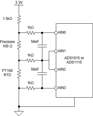
    I put together something a little different that what you had put together. It uses a voltage excitation in a stack of resistors. I'll show it, explain how it works, some potential error sources, and you can see if this is something you could use.

    First here's a basic schematic:

    There are 3 resistors, which includes the PT100. First, there's the PT100 that varies from about 104Ω to about 119Ω in the range that you care about (10°C to 50°C). There's a precision 100Ω resistor. This is basically the reference resistor that we compare the PT100 measurement against. Then theres a 1.5kΩ resistor that we use to take up some of the voltage from the supply. By using this, we can keep the 100Ω resistor measurement and the PT100 measurement under the ±0.256V FSR. I would note that this setup uses a bit more current, but the change in the PT100 voltage is now almost 28mV, which is a bit larger to see.

    I then constructed an excel spreadsheet to show what voltage you would get across each resistive element.

    This would give you the following voltages across the resistor and the PT00:

    You can see that the 100Ω resistor voltage doesn't change much (about 14 codes through the range of 10°C to 50°C), but the PT100 voltage has a much larger change. It changes over 200 codes over this temperature range. This is basically a resolution of about 0.2° per code.

    To get the PT100 resistance, we measure the 100Ω resistor, then measure the PT100, and get both ADC codes. If the 100Ω resistor is precise. Then we can use this equation:

    PT100 resistance = 100Ω * (PT100 measurement/100Ω measurement)

    There's a couple of advantages to this setup. First, we only need the ration between the two codes. We don't have to convert to voltage. Note that the measurment is precise as the accuracy of the resistor (you'll want a resistance that's 0.1% or better). Second, the supply voltage doesn't need to be precise. If the voltage is higher than expected, the two measurements will be higher by the same percentage. This error falls out in the ratio. Next, because the device uses a multiplexer, the gain error from channel to channel will track.

    Looking at the schematic, I keep the differential filtering but removed the common-mode filtering. In this because of the setup, I'm not sure there's a way to duplicate the common-mode filtering for both channels. I would also note that the series 1kΩ resistance might cause some gain error because the input impedance is low for this device in that range (about 710kΩ - I'd forgotten it was this low in this range). I would note that this gain error would also likely track for both measurements. However, just to be safe you might want to lower the resistace even further.

    I'll attach the excel file to this post. You can review it and play with the numbers.

    Joseph Wu

    PT100.xlsx

  • Hello Joseph,

    thank you for the suggestion, I will definitely look into it.

    Riccardo