This thread has been locked.

If you have a related question, please click the "Ask a related question" button in the top right corner. The newly created question will be automatically linked to this question.

ADS1283: FIR design

Part Number: ADS1283

Dear support team,

We bought a seismic acquisiton system using the ADS1283 and I was surprised by the phase delay applied by the FIR stages in data.

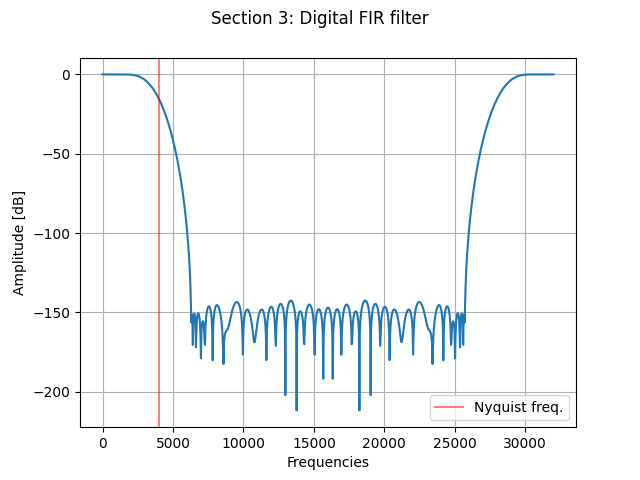
On section 3 and section 4 (linear phase) detailed in Table 9, the detailed FIR would have a symmetrical shape if some zeros (2x on section3 and 1x on section4) was'nt added at the end of the coefficients array. It doesn't bring anything on the amplitude but affects the phase delay, which is no more corresponding to the theory ( phase_delay = (N-1)/2 samples ). This is why my system is affected by this additional phase delay. Why did you designed it that way? Is there a practical reason? From my point of view, it brings nothing except more phase shift..

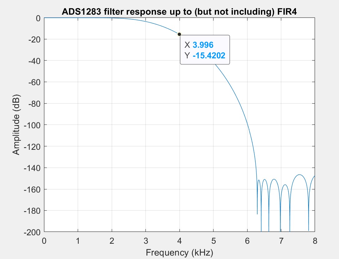
I also noticed about the coefficients that all sections except last one does not filter all frequencies below Nyquist frequency. It seems to me a big twist on Nyquist theorem. So my second question is almost the same: is there any good reason to design your filters such a way?

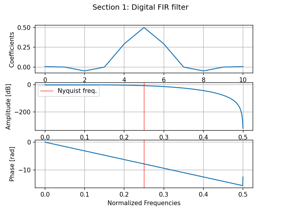
I included below the fft plot of section 1 (decimation factor 2, so should filter below 0.25)

Thanks a lot for your support.

Max

  • Hi Max,

    Welcome to the TI E2E Forums!

    I've sent a request to our design team to inquire about the rationale for the additional zero coefficients which add to the overall phase delay. I'll provide an update once I hear back from them.

    Regarding the other two comments/concerns about the digital filter:

    • For the linear phase FIR filter, the added zeros shouldn't affect the phase linearity; however, they will add to overall phase shift as you mentioned.

    • Regarding the last filter section, expect for a small passband ripple I'm not exactly sure what you mean when you say that that this filter does not filter all frequencies below Nyquist...When I plot the amplitude response of the fourth filter stage, this is what I get:

      This is the response of just the 4th FIR filter stage for the 4kSPS data rate. The cuttoff frequency is around 1.65kHz. Keep in mind that the ADS1283 FIR filter is a multi-rate filter where each section decimates the input data rate into the next filter stage. Therefore, the passband repeats at integer multiples of the input data rate (8 kHz for the last filter stage). However, when you combine the responses of all filter stages, the overall response will not include the reflected passband of the 4th stage FIR filter, as shown below:


  • Hi Chris,

    Thanks for your response.

    I truely agree with you, but my concern is around the previous FIRs.

    For an overall output sps at 4kHz, let's take the 3rd FIR section.

    Its input data rate is at 32kHz (comes after sinc filter at decimation 8, and 2 FIR filter sections at decimation factor 2 each). Its decimation factor is 4. Therefore, it must filter any frequency below 32 kHz/8 = 4 kHz, to be allowed to decimate at 8 kHz.

    But it filters properly only for frequencies below ~6.3 kHz (see image attached). This concern also applies to 1st and 2nd FIR section.

    Regards,

    Maxime

  • Hi Maxime,

    I'm not sure I follow along with the reason why the third FIR filter stage would need to have such a large attenuation at 4kHz. If you have any resources that you could point me towards to learn more I would welcome that!

    However as I understand it, the third FIR filter stage is receiving sampled data at 32kSPS and outputting data at 8kSPS. The third filter stage has a bandwidth of 16kSPS, where as the 4th filter stage only has a bandwidth of 4kSPS. The third filter stage is already proving some noise attenuation around 4kHz (though it is only -15 dB); but then in the fourth filter stage 4kHz will be attenuated much more significantly.

    Therefore, I don't think there is any concern regarding noise aliasing since the Nyquist frequency is getting attenuated more and more with each additional filter stage.

    I hope that helps!

  • Hi Chris,

    Thanks for your answer.

    OK, regarding your comments, I just understood something:

    Does the global decimation process (ie. picking one sample out of 32) come after the global filtering process (ie applying all filter stages)?

    In that case, it makes sense and you're right the 4th filter stage will attenuate every remaining aliasing noise due to lower attenuation of previous stages. I thought an intermediate decimation was done after each stage...

    Do you have any feedback about the trailing zeroes in coefficients on stage 3 and 4?

    Regards,

    Max

  • Hi Max,

    Each filter stage should be applying a decimation before data is provided to the next stage, which means you can model each successive filter stage as having a decreasing sampling rate that is decreased by the decimation ratio of the previous stage. So it is not a global decimation, but each filter stage is utilizing all of the filter taps before data is decimated.

    Unfortunately, the original designer of this filter is not around to answer this question.

    My best guess at this time is that these additional zeros are not significantly impacting the settling time of the device. The 3rd FIR filter stage decimates by 4, so its delay is less than 1/2 sample at the 4 kSPS output data rate (i.e. <1 sample delay between stage 3 and stage 4 since the 3rd stage decimates by a factor of 4, and then the 4th stage decimates by another factor of 2). Also, the ADC will introduce some additional digital delays AFTER the filter in order to apply the calibration scaling factors, load the data into an output shift register, and the set /DRDY pin low. These extra delays after the digital filter are happening in parallel with the next conversion result (like a pipelined processor). Therefore, even without the extra zeros in the filter coefficients, I'm not sure if you would see any increase in the output data rate, but if so it would probably result in very strange data rates like 3.963 kSPS, for example.