This thread has been locked.

If you have a related question, please click the "Ask a related question" button in the top right corner. The newly created question will be automatically linked to this question.

DAC161S997: how to power DAC

Part Number: DAC161S997
Other Parts Discussed in Thread: LM2841

Dear :

          i use DAC161S997 as a converter , transfer SPI data to 4-20mA. now it can work. but I found one issue, in order to describe it exactly,let me separate power on device with 2 different steps.

         step 1: connect loop + and loop - with power adapter.             step2:  connect adapt to power.

         if follow step1first, then step2. it is ok, anything runs smoothly, if reverse 2 steps, step2 first, then step1.DAC output will change,  such as 12mA or any other number, normally, DAC should give 4mA at zero input . after change DAC , output back to normal,  2 pcs DACs and 1 triode have failed like this . can i know what's the reason? how should i do when i use DAC? 

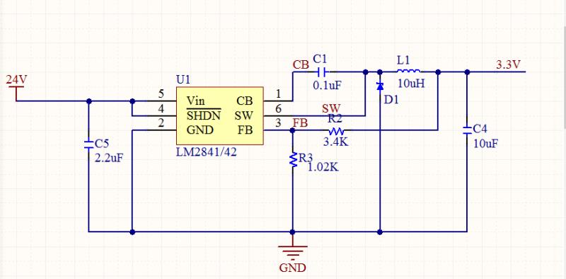
          my schematic as below 

  • Hello Jeffrey,

    I am glad you are now able to communicate with the DAC successfully. Can you explain why you are testing the startup using the normal method and then the reverse scenario?

    With the first case seems like what I would normally expect, with the loop supply ramping up cleanly, which will in turn generate 3.3V from the LDO, which will enable the DAC and establish the correct loop current.

    I believe that the reverse scenario, you are likely introducing a lot of glitch initially on the loop+, loop- terminals depending on which one is connected first. This causes the loop to startup in a wrong state. 

    What do you mean by 'two DACs failed'? For those parts, if you power up the device in the normal way, is the loop current established correctly or do the DACs permanently fail after the reverse test?

    Regards

    Reza

  • Dear Reza :

                thanks to your professional support, I can use DAC now, although, still some small issues need I work out.

                about "two DACS failed" mean it can't work properly, as I described, it's output deviated from normal, even I repower it with normal way. I think, DAC permanently fail. 

                I am not testing DAC with the reverse scenario . just because I have not attended startup consequence, power it randomly. after first DAC failed, i think, maybe something wrong that i don't know, i didn't care it . when second DAC failed, i guess, maybe power impact it. 

                After launch this product, i can't tell the customer you must attend it, because we can't control the operator follow it 100%.  so need your to support , what i can do on power or schematic? Does wrong startup action will impact other components such as the triode . 

               Have a nice day and take care in this special period.

    thanks!


  • Hello Jeffrey,

    Given the fact that both the external NPN and DAC seem to be damaged, I suspect that connecting the loop + and loop- using the second method caused intentional large transients that exceeded the abs max rating of NPN and subsequently, the DAC. Some protection is required for the circuit. I took another look at your design and I have the recommendations below. I may have already recommended some of these updates in an earlier discussion

    1. Place a zener between NPN collector and input of LM2841. This will ensure that the switcher can start up correctly at lower supplies and will provide some protection for the NPN against excessive transients

    2. Place a diode (schottky preferred) between loop+ and input of switcher. This is to enforce current flow direction which may offer some protection against reverse transients

    3. Place another diode between OUT pin and loop-, also to force loop current direction at startup.

    4. Place TVS diode between loop+ and loop- to limit startup transients when starting the loop. TVS reverse breakdown voltage should be slightly higher than the maximum loop power supply. 

    Regards

    Reza

  • Dear Reza :

                   thanks for your suggestion. let me try it as your advices.

                   actually, I have added one Zener into the circuit (advice 1) since we last spoke, but DAC still impacted. By the way, can I use one capacity (such as 50V 1uF ) instead of TVS diode between loop+ and loop-? in order to filter high voltage. 

    thanks!

    Jeffrey 

  • Hello Jeffrey,

    I do not think a 1uF capacitor will work as well as a TVS diode between loop+ and loop-. I also recommend adding the schottky diodes like I mentioned earlier. These protection components should resolve the issue if there really is an over voltage event occurring when connecting the loop supply. 

    Thanks

    Reza

  • HI    Reza :

                  sure ! 

                 let me try with your suggestion .

                 thanks your great support .

    have a nice day !

    thanks 

    Jeffrey