This thread has been locked.

If you have a related question, please click the "Ask a related question" button in the top right corner. The newly created question will be automatically linked to this question.

ADS1235EVM: Ratio metric reference setup

Part Number: ADS1235EVM
Other Parts Discussed in Thread: ADS1235, , UCC27524

Hi,

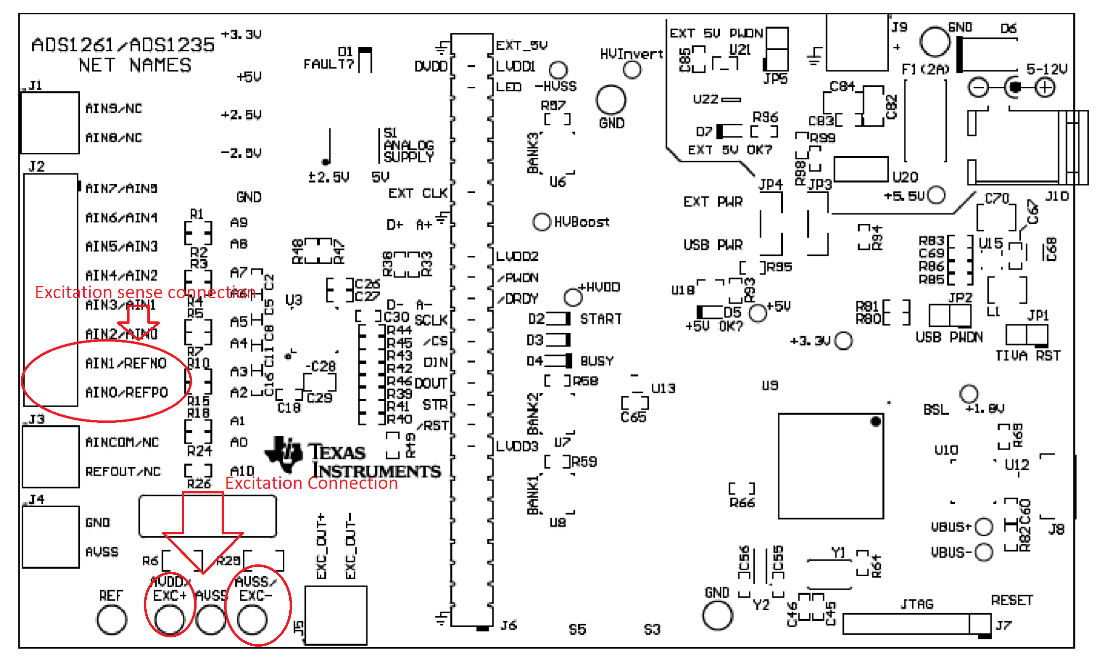
I am looking at setting up an eval kit with a ratiometric reference. It looks like the ADS1235 allows for this with the REFN0 and REFP0 pins and that we should be able to use J2 pins 7 and 8 to connect a 6 wire load cell sense lines. unfortunately, I don't see any mentions of voltage reference vonfiguration in the eval kit documentation and since the system works with arbitrary inputs it would suggest that the eval kit is using the internal ref of the ADS1235.

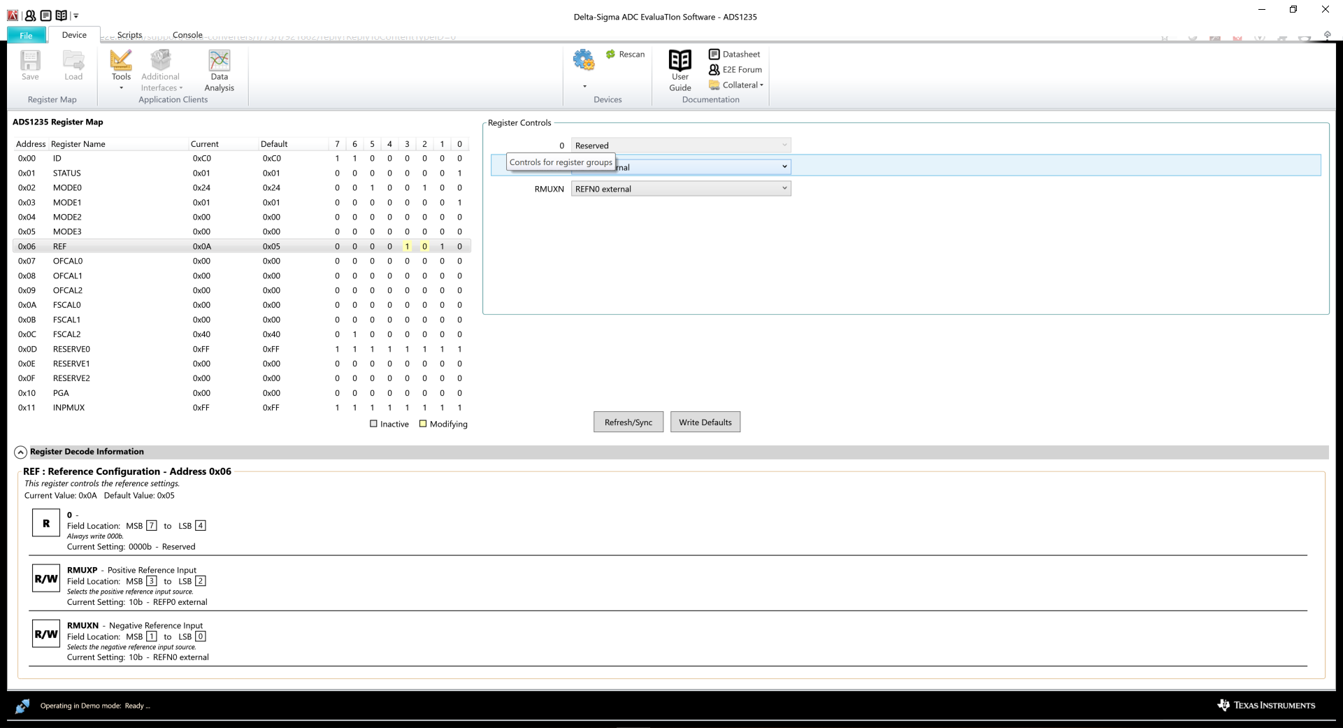
Since there are no register maps can you tell me how to disable the internal refference? Is there a command or can we make some other modification?

Thanks,
Adam

  • Hi Adam,

    For the ADS1235EVM you can connect the excitation wires to the test points AVDD/EXC+ and AVSS/EXC-.  You can connect the excitation sense wires to REFP0 and REFN0 using J2 pins 7 and 8.  The signal wires can connect to the inputs of your choice.

    In the ADS1235EVM GUI you would set the register settings for the reference as shown below:

    Best regards,

    Bob B

  • Hi Bob,

    Thanks for the help! We got the DC working, but I am now trying to configure the AC excitation and I can’t get it to work correctly. The sampling software either shows a very noisy signal or a flat line with infinite ENOB and NFB. I have attached a photo of my register setup as well as the wiring, and am wondering if you have any suggestions on how we could get it to work.

    Thanks,

    Adam

  • Hi Adam,

    It is a bit tricky to setup the AC excitation.  Note that for the driver chip used you need to use the non-inverting signals to drive the UCC27524.  I have attached the note that corresponds to the setup from the user's guide schematic:

    So you need to be in 4-wire mode but only enable GPIO2 and GPIO3.  Take a look at the script file 'Enable bridge - external reference w/AC excitation' to compare your register settings with those of the script and in particular registers 0x3, 0x4 and 0x5.

    Best regards,

    Bob B