This thread has been locked.

If you have a related question, please click the "Ask a related question" button in the top right corner. The newly created question will be automatically linked to this question.

ADS7052: Build up a test environment for 14 bit ADC

Part Number: ADS7052
Other Parts Discussed in Thread: DAC91001, ADS7056, OPA836, ADS7046

Hello, 

I would like to build up an ADC test environment that can achieve about 14 bit from 1.65 V to 3.60 V. So I choose ADS7052 as my develop tool.

The attached file is my first edition schematic, it's very appreciate that could give some suggestion and correction about this schematic.

thank you!!

Wen

Imitate ADS7052.pptxImitate ADS7052.pdf

  • Hello Wen,

    looking at your schematic, below are my notes

    1.Increase the AVDD decoupling capacitor. the datasheet states to use a 3.3uF, 

    2. the capacitors at the input are too big. What is the source of the input, and is there a driving op amp. I would suggest removing all the capacitors and replacing with a capacitor in the few hundreds of pico farads

    Regards

    Cynthia 

  • Hello Cynthia :

    Thank you for your kindly reply! and base on your notes, 

    >> What is the source of the input?

    For dynamic test : the source of ADC may come from Audio precision directly without capacitor on the input path.  

    For the static or linear test : the source of ADC may be considered from 18 bit un-buffered DAC such as DAC91001 to generate a ramp from 0 to AVDD. However, I am trying to study its datasheet and evaluate board documents. Could you give me a little time for ready DAC91001 circuit then have a discussion with you? or do you have another suggestion about linear test for 14 bit ADC ?

    A question about fetch data, since ADS7052 have a PHI board that covers EEPROM & GUI for analyzing FFT result, may I use this develop tool to fetch data and analyze them ? Thank you!

    B.R 

    Wen

  • Hello,

    Apologies for the late response 

    I hope you were able to move forward.

    I believe if you did as recommended: removed all the input caps, and replaced is a hundreds of pico farads cap you should have been able to complete the test.

    As for the DAC91001, it seems it will need a buffer amplifier at the output to drive the voltage. If you do not use a buffer, and connect the DAC directly to the ADC, this might lead to settling errors. These errors will get worse at faster sampling rates.

    Yes, the EVM and GUI of the ADC can help collect data and analyze it. the EVM also has on board amplifiers that can be used to drive the signal from the DAC to the ADC

    Regards

    Cynthia

  • Hello Cynthia :

      Thank you for your kindly advice.

      I'll replace the input capacitor with pF.

      A question about those input capacitor that there is a document said drIving an ADC without driving OPA ( show as Fig.87 ).


      https://www.ti.com/lit/ds/sbas539b/sbas539b.pdf?ts=1598323807578&ref_url=https%253A%252F%252Fwww.google.com%252F


      It said that 'drIving an ADC without driving OPA' often use for low power or low speed apply.

      However, if I want to evaluate ADS7052 ( 1 MSPS ) and ADS7056 ( 2.5 MSPS ), should I add OPA836 as an input driver for high speed apply ?

      My input source is from Audio precision ( APX-525 )

      The reason of I chose OPA836 is that 

      1. OPA836 has high slew about 560 V/us

      2. Phase margin at gain = 0 dB is about 73 degree ( show as attach file )

      3. ADS7046 ( 12 bit ) is recommend that add a driver with OPA836 

      Thank you!

    B.R

    Wen

  • The application for not using an op amp does not apply here. This is for low sampling rates with a source that is usually a type of sensor. 

    If you would like to operate the device at high sampling rates then a driving op amp would be necessary. 

    The OPA836 is a very good option, this device has a gain bandwidth 118MHz which is more than sufficient to drive the input at max throughput.

    Regards

    Cynthia

  • Hello Cynthia :

      Thank you for your detail reply!

      Since my input signal will be a sin wave about 1k ~ 10 kHz .

      It seems not a very fast signal that need to be drived with OPA.

      Another question about ADS7052 operated with low voltage.

    1. What are SCLK, CSB and SDO 's reference voltage level ( track from DVDD or an internal level shifter ) ?  

    2. If I select AVDD = 1.65V, DVDD = 1.65V, should I let my control signal such as SCLK, CSB,.. operated at 1.65V ?

    3. If the second case is not suggested, may I try a case about AVDD = 1.65V, DVDD = 3.6V without a level shifter for I/O interface ? ( my control signal is about 3.3V )

      Thank you!

    B.R

    Wen

  • You are correct, an input op amp might not be needed at those low frequencies 

    1. The ADS7052 digital output communication pins are pulled high to the DVDD voltage; the input digital pins will use DVDD voltage as the reference voltage for the device to decipher a low or high state. 

    2.Correct, the digital pins should operate at the DVDD voltage. The AVDD voltage has no influence on the digital communications of the device. 

    3. The power supplies, AVDD and DVDD are independent of each other. This means DVDD can be set at any voltage, regardless of AVDD voltage. Thus in this case, DVDD can be set higher at 3.6V while AVDD =1.65V. this would be acceptable. 

    Regards

    Cynthia

  • Hello Cynthia:

      Sorry for delay reply and thank you for your detailed answer!

      Since the logic analyzer need to be set at a specific trigger level and DVDD is not an impact factor that'll degrade the performance. 

      Fixing DVDD at 3.3V will be friendly for the environment.

      It's vary thankful that your advise for this apply circuit! I'll try to implement this circuit on PCB, thank you !! 

      May I bother you some questions about INL and absolute error ? 

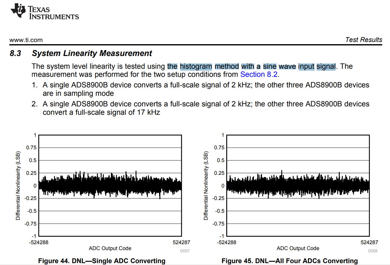
      From this picture, it said we can get DNL and INL by histogram of sine method.


      However, if I want to estimate accuracy such as 2^( ideal bits )  - log( absolute error ) but not ENOB...

      Could you share me some ideal of how to estimate absolute error ? 

      Thank you !

    B.R

    Wen

  • Glad it was helpful

    There is a good blog about Total Unadjusted Error, that I think can explain, it is art 2 of a three part blog, if you would like to look at the other parts as well. 

    If if you till have questions please let me know 

    Regards

    Cynthia