This thread has been locked.

If you have a related question, please click the "Ask a related question" button in the top right corner. The newly created question will be automatically linked to this question.

ADS131A04: External Reference: Internal buffer bypass

Part Number: ADS131A04
Other Parts Discussed in Thread: OPA189, OPA837

Hi Support Team,

For the ADS131A04 reference, I understand that VREF is supplied internally and can be set to either 2.442V or 4.0V. 
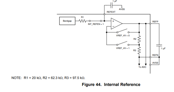
by default, VREF is externally supplied via REFEXT. In both cases, the reference is internally buffered...

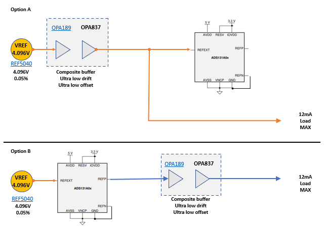
My question, is it possible to bypass the internal buffer and supply external VREF @ REFP pin?

The reason I ask is I am using a precision 0.05%, ultra low noise (< 10 nV/vHz), low drift (< 5 PPM/°C)external reference and a composite buffer circuit.
However, I am afraid the external buffer performance is limited by the internal buffer. 

The application calls for 1% and 0.1% FS accuracy pre/post calibration. Inputs are uni-polar {0v-4V}


Best,
AJ

  • Alex,


    The reference buffer can't be disabled. If you try to drive the REFP with an external reference, the reference buffer output will try to drive the node as well. You can only use the REFEXT pin for the external reference.

    However, I'm not sure this is as bad as you think. The reference buffer offset is only ±250uV typical. On a 4V reference, this would cause a gain error of approximately ±0.006%. There will be some spread to the reference buffer offset, and there's an additional offset drift of about 4uV/°C. Both will make the gain error spread wider. However, the gain error associated with this offset drift will be smaller than the reference error of 0.05%.


    Joseph Wu

  • Hi Joseph,

    Thank you for clarification. Initially I was thinking to minimize drift and offset errors as shown in the option A.
    I suppose I could buffer REFP out and supply the load with precision reference as per Option B


    best,
    AJ

  • AJ,


    Sorry I missed this post last week. I'm not entirely sure how you want to use the reference, but if you are using the reference (with the 12mA load) to drive a bridge measurement and would like the ADC to make a ratiometric measurement, then Option A would be better.

    Option A has the internal reference buffer as part of the error, while Option B has both the internal reference buffer and the composite buffer as contributors for the error.

    Is that what you were asking? What sort of measurement are you making? I think a bit more information might help.


    Joseph Wu

  • Hi Joseph,

    Thank you the insight. You are correct, we are powering a string of sensors for ratiometric type measurements

    Since internal buffer can not be bypassed as you pointed out, I want to include internal reference error to the load.

    Therefore, I believe Option B not A would be the better option, i.e. buffered reference to the Load would be closer to what the ADC actually sees 


    Option A:
    ADC sees VREFext + ΔVREFext +  Err(internal buffer offset / drift )
    Load sees VREFext + ΔVREFext 

    Option B: 
    ADC sees VREFext + Err(internal offset / drift)
    Load sees VREFext + Err(internal offset / drift)ΔVREF 

    ΔVREF << Err(internal offset / drift)  - from the specs, we have:

    Err(Internal buffer)
    Offset: ±250µV             TA = 25°C
    Drift:    ±7µV/°C        –40°C ≤ TA ≤ +125°C


    ΔVREFext [OPA189]:
    Offset:  ±4µV            –40°C ≤ TA ≤ +125°C
    Drift:     ±0.02 µV/°C –40°C ≤ TA ≤ +125°C


    Best,
    AJ

  • AJ,


    I see your point. I'd forgotten that for this device the REFEXT may be the input of the reference, but the REFP really where the ADC draws the reference input. This is the more important point for the measurement (This is a little unusual in comparison to some of the other devices we have).

    With the ratiometric measurement, the voltage does not need to be accurate, but it is important that the ADC reference input and the voltage driving the ratiometric measurement are as close as possible. Now that I've had a chance to review it more closely, I believe that you're correct and option B is the more accurate option.You can see it comparing the ADC reference to the ratiometric sensor drive.

    With option A, your error comes from the ADC's reference buffer. The buffer error is part of the ADC reference, but not part of the ratiometric sensor drive.

    (reference input+ADC ref buffer error)/(reference input)

    With option B your error is different:

    (ADC ref buffer output)/(ADC ref buffer output + external buffer error)

    Here, the only difference between the ADC reference input and the ratiometric sensor drive is the external buffer error.

    Even with the combination of the OPA189 and the OPA837, the offset should be much smaller than the offset error of the ADS131A04 reference buffer. Because of this, option B would have the smaller error.


    Joseph Wu

  • Hi Joseph,

    Thank you for taking the time to review and confirm :)


    Best,
    AJ