This thread has been locked.

If you have a related question, please click the "Ask a related question" button in the top right corner. The newly created question will be automatically linked to this question.

AMC1336EVM: Bitstream shows DC-component at pure AC input signal

Part Number: AMC1336EVM
Other Parts Discussed in Thread: AMC1336, AMC1306M05

Hello,
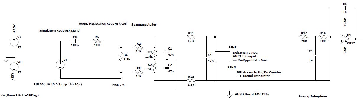
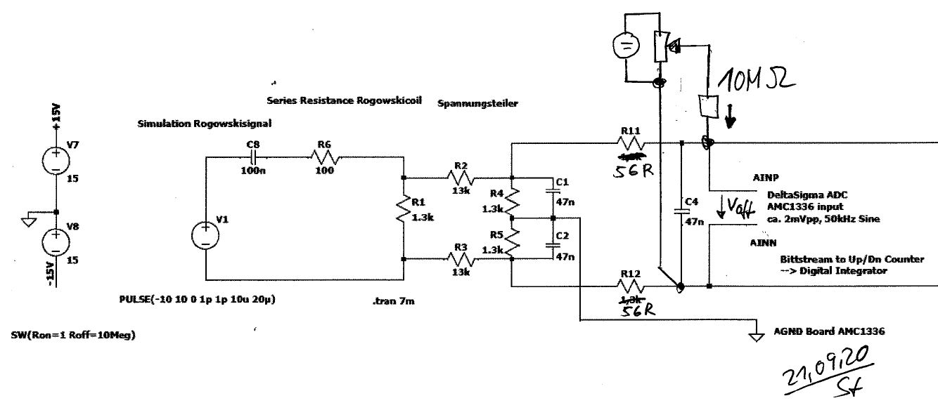
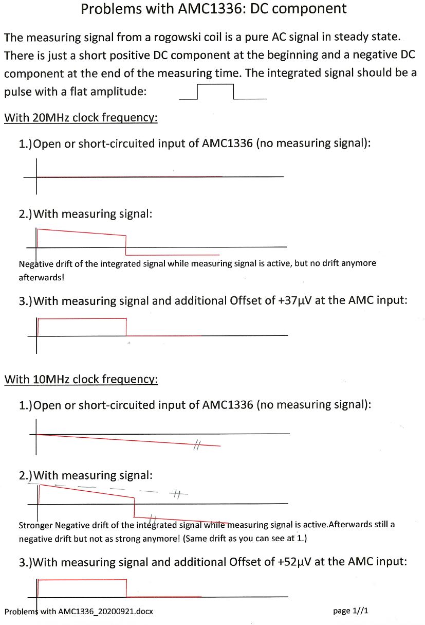
in our application we find that despite a pure AC-input signal on the AMC1336 (approx. 2mVpp, 50kHz) the bitstream output delivers a DC component corresponding to a DC-input of approx. 50µV.
In case of no AC-input signal the bitstream output is exactly 50% --> no DC component!
Today's measurements show that DC-component also arises when we change the clock from 20MHz to 15MHz.  The same applies to a larger input signal e.g. 40mVpp.
The bitstream is evaluated by an up/dn-Counter (per FPGA, no sinc-filter!) and in case of the DC-error the counter keeps counting up.
We intentionally use very small input signals so as not to get into the range of high integral non-linearity (Fig. 7, datatsheet  / printing error: Vin(mV)  --> V? )
Do you have any idea to fix the error?
Are there DeltaSigma ADC available with better accuracy and bitstream output, maybe without galvanic isolation?
Thank you.
Karl
  • Hi Karl,

    Welcome to our forum!  It would appear as though you had attempted to include a plot or something with your post.  Can you resubmit that?

  • Hello Tom,

    yes I tried to provide a circuit diagram for the signal conditioning.

    Hope, now you can see the drawing.

    KArl

  • Hi Karl,

    I'm going to do a simulation of this in TINA to take a closer look. In the meantime, a few possible sources for this DC shift could be mismatched resistors or capacitors in your signal conditioning circuit, or the small amount of bias current from the AMC. 

    Do you have more detail about the DC shift you describe? How are you calculating this from the output of your counter? Do you see any difference in the DC shift when using the 15Mhz and 20Mhz clocks or does it have the same magnitude for both clock frequencies?

    Regards,

  • Hi Scott,

    here are some more informations about the AMC1336 problem:

    We want to use the AMC1336 as an integrator for rogowski current measurement signals. The current pulses have a duration from ca. 1ms up to some seconds.

    In the actual measurements we notice the described DC-component in the AMC1336-bitstream and we can eliminate the drift by inserting a very small additional DC-Current at the input of the AMC1336 (see drawing) resulting in an offset Voltage "Voff" of 37µV / 52µV .

    We have made some further measurements:

    This is very strange:

    • there is a different behaviour between 20MHz and 10MHz Clock
    • with 20MHz clock we have no drift at "no measuring signal" (1) and despite 37µV Offset-voltage after the current pulse (3)
    • with 10MHz clock the drift is only removable with Offset-voltage 52µV

    It looks like a hysteresis, but as the AMC1336 is an integrating DeltaSigma-ADC there should be no hysteresis.

    Regards

    Karl

  • Hello Karl,

    I appears that you are measuring the offset error of the AMC1336. Referring to Figure 12 from the datasheet, you will find that the offset error does change with the clock frequency. The roughly 20uV difference in the offset between the two clock frequencies is certainly possible given the data from our characterization.

    There are a few ways to combat this. First you could add an integrator or preamp before the input to the AMC1336, or you could add some calibration to compensate for the offset. 

    Also, have you considered using a different device with an input range that better matches your signal? You are giving up quite a bit of dynamic range with the AMC1336. The AMC1306M05 has a +/-50mV input range that would be closer to your +/-2mV signal.

    Regards,

  • Hello Scott,

    thank your for the reply.

    Yes, with Fig 12 the change in the offsetvoltage at varius clock frequency is understandable.

    But, we do not understand the arising dc component when applying our small ac-input signal.

    • Do you have an explanation for this?

    Of course , we have checked the other AMC13xx if they are suitable for our application. But the  AMC1306m05 has an input bias current of -72µA!!  (AMC1336 ±3nA) and a very low input resistance 4,9kOhm!! (AMC1336 1,5GOhm) --> this will produce additional errors.

    For better  resolution we can increase the amplitude of the input signal and we will make a measurement. The intention of the small input signal was to avoid the problem of integral nonlinearity (Fig. 7).

    Regards

    Karl