I need to fit an ADS1294 onto a very small PCB to measure 3 bipolar inputs for a biomedical application: EEG (technically, ECoG), EMG, and ECG. The input filtering components are a burden to my BOM, so I am exploring the idea of removing non-essential components. My understanding is that the capacitors connected to AGND (Figure 96. Typical Front-End Configuration) are for antialiasing, whereas Cdiff (between the electrodes) is a differential RC filter. My signals of interest—most importantly, on the ECoG channel—are 0.5-4 Hz, so even at the lowest sampling rate, I wouldn't expect antialiasing to affect my data, is that true? Here is my proposed schematic (VDDA = +1.5V, VSSA = -1.5V, GNDA and GNDD are tied at a single point).

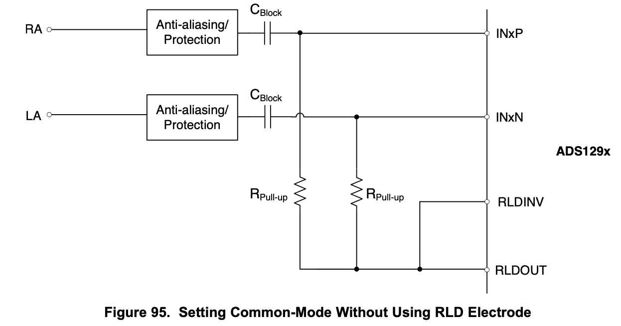
My second question is more generally regarding the RLD use. Given my configuration, I'm not sure what will be 'common' and if the RLD electrode will be useful (It's also very likely that I measure one electrode channel at a time to minimize power consumption). I'm wondering if following Figure 95. Setting Common-Mode Without Using RLD Electrode—using DC blocking caps—would be advised instead? Although, that would also add significantly to my part count.
Below is my electrode configuration. If I can make use of the RLD, it would be a small paddle-style electrode, but again, I'm not sure I expect much to be 'common' about my ECoG and EMG channels/electrodes. Unfortunately, this is a hard circuit to simulate/bench test/tinker with, so I'm looking for some educated input before testing. Thanks,

Other posts:
[FAQ] ADS129x: How do I calculate the DC gain of the RLD or BIAS amplifier?
ADS1298: How to properly bias an animal recording brain/cardiac signals?
ADS1298: PCB questions (capacitors and power supply)
Aliasing in ADCs: Not all signals are what they appear to be
ADS1298 - filtering inputs signals