Howdy,
I've recently inherited an ADS42JB69EVM board in our lab group and I'm experiencing an issue when attempting to digitize incoming information from an emulator. The emulator is a CAEN DT5810D providing information via a BNC cable with an adapter to the SMA fitting on the EVM board. Ultimately, the goal is to digitize tail pulses coming out of a preamplifier hooked to a radiation detector, then pass them through a TSWTSW14J10 to a KC705.
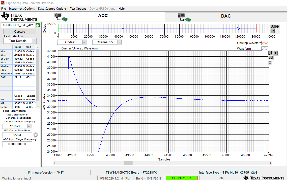
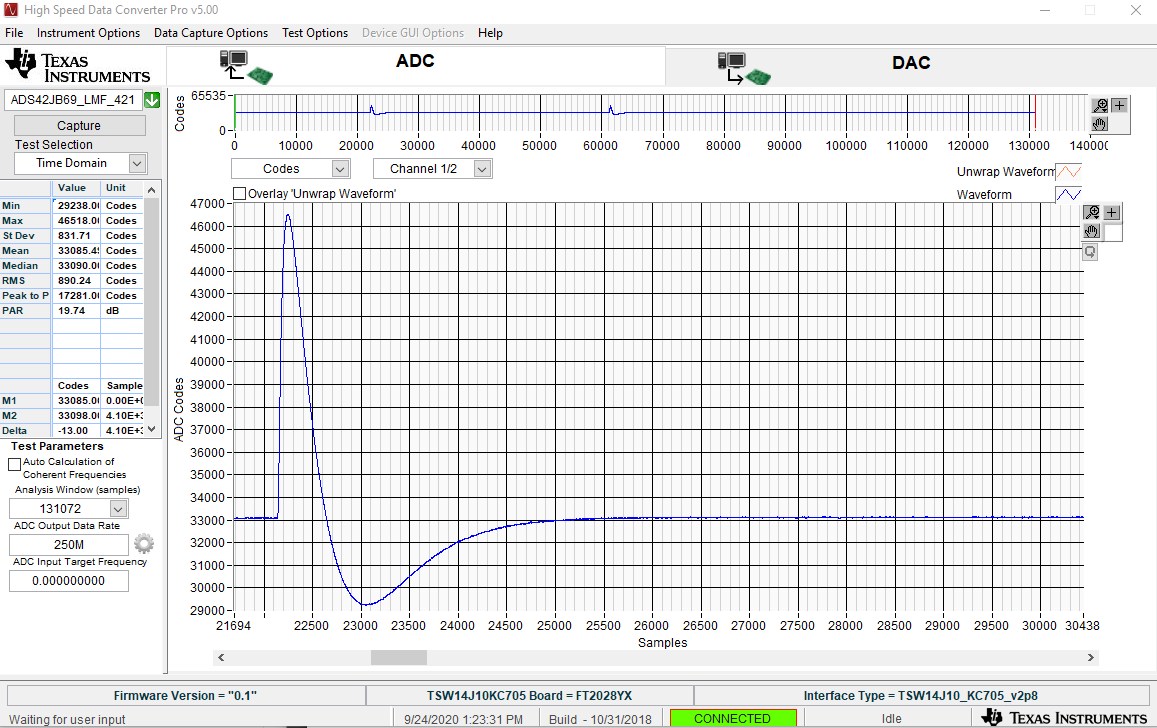
Whenever I try to digitize a tail pulse, the resulting signal exhibits bipolar characteristics (see below). I have tried inserting a 50-ohm BNC terminator on a T-junction with the input signal and the BNC-to-SMA adaptor in case it was an impedance problem, but that simply reduces the magnitude of the signal and does not change the shape. The configuration file should also be found below.
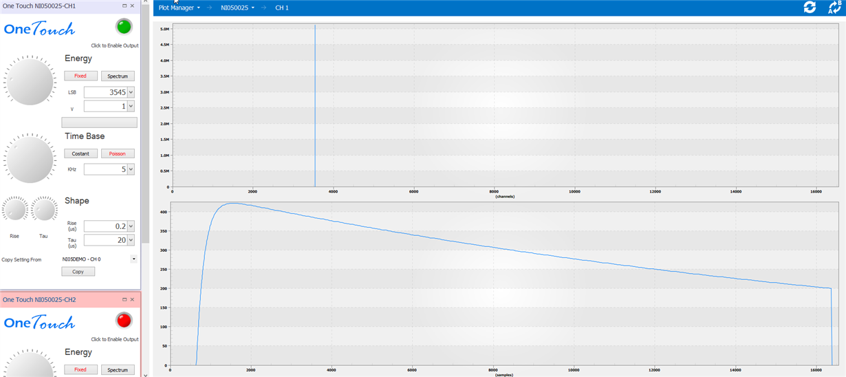
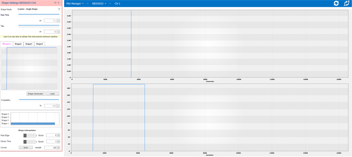
I've included examples of the source pulse and the resulting digitization seen through HSDC Pro below; any guidance you can provide as to what might be going wrong would be appreciated.
Digitization of tail pulse with tau_rise = 200ns, tau_decay = 20us:
Digitization of rectangular pulse with width = 20us
Configuration File
LMK04828
0x00 0x10
0x02 0x00
0x100 0x0C
0x101 0x55
0x103 0x00
0x104 0x20
0x105 0x00
0x106 0x70
0x107 0x11
0x108 0x6C
0x109 0x55
0x10B 0x00
0x10C 0x20
0x10D 0x00
0x10E 0x71
0x10F 0x66
0x110 0x00
0x111 0x00
0x113 0x00
0x114 0x00
0x115 0x00
0x116 0x08
0x117 0x00
0x118 0x6C
0x119 0x55
0x11B 0x00
0x11C 0x20
0x11D 0x00
0x11E 0x78
0x11F 0x61
0x120 0x0C
0x121 0x55
0x123 0x00
0x124 0x00
0x125 0x00
0x126 0x71
0x127 0x01
0x128 0x00
0x129 0x00
0x12B 0x00
0x12C 0x00
0x12D 0x00
0x12E 0x08
0x12F 0x66
0x130 0x0C
0x131 0x00
0x133 0x00
0x134 0x00
0x135 0x00
0x136 0x08
0x137 0x00
0x138 0x24
0x139 0x03
0x13A 0x01
0x13B 0xE0
0x13C 0x00
0x13D 0x08
0x13E 0x00
0x13F 0x00
0x140 0x00
0x141 0x00
0x142 0x00
0x143 0x31
0x144 0xFF
0x145 0x00
0x146 0x18
0x147 0x1A
0x148 0x10
0x149 0x54
0x14A 0x33
0x14B 0x16
0x14C 0x00
0x14D 0x00
0x14E 0x00
0x14F 0x7F
0x150 0x03
0x151 0x02
0x152 0x00
0x153 0x00
0x154 0x78
0x155 0x00
0x156 0x0A
0x157 0x00
0x158 0x96
0x159 0x00
0x15A 0x64
0x15B 0xD4
0x15C 0x20
0x15D 0x00
0x15E 0x00
0x15F 0x0B
0x160 0x00
0x161 0x01
0x162 0x44
0x163 0x00
0x164 0x00
0x165 0x0F
0x166 0x00
0x167 0x00
0x168 0x0F
0x169 0x59
0x16A 0x20
0x16B 0x00
0x16C 0x00
0x16D 0x00
0x16E 0x13
0x17C 0x15
0x17D 0x0F
ADS42JB69
0x06 0x80
0x07 0x00
0x08 0x18
0x0B 0x00
0x0C 0x00
0x0D 0x90
0x0E 0x90
0x0F 0x00
0x10 0x00
0x11 0x00
0x12 0x00
0x13 0x00
0x1F 0x7F
0x26 0x06
0x27 0x03
0x2B 0x00
0x2C 0x00
0x2D 0x13
0x30 0x20
0x36 0x00
0x37 0x00
0x38 0x00
FPGA
0x04 0x00
0x05 0x00
0x0E 0x00
0x0F 0x00


