This thread has been locked.

If you have a related question, please click the "Ask a related question" button in the top right corner. The newly created question will be automatically linked to this question.

AMC1210MB-EVM: AMC1210EVM+ACM1305EVM test problem

Part Number: AMC1210MB-EVM
Other Parts Discussed in Thread: AMC1210,

Hi team,

I was using AMC1305EVM and AMC1210EVM for testing and found some questions that puzzled me.

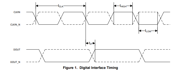
The test circuit diagram is shown in the figure:

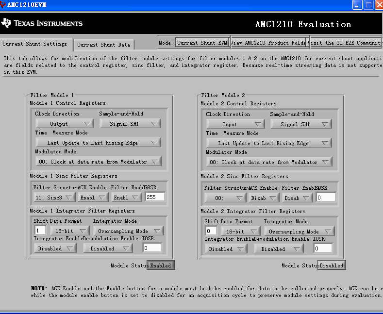
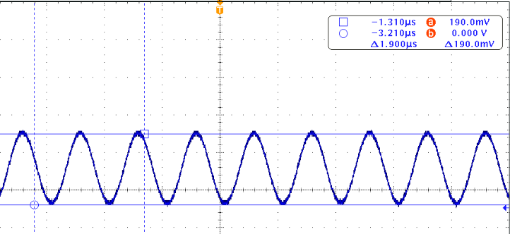
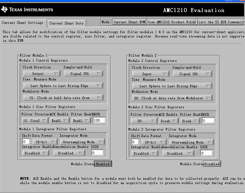
The input of AMC1305 is 200mv sine wave,Through the AMC1210 software settings, as shown in the figure below:
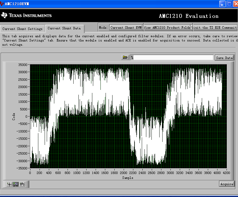
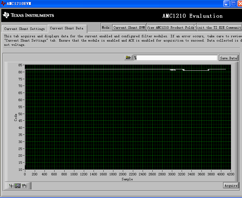
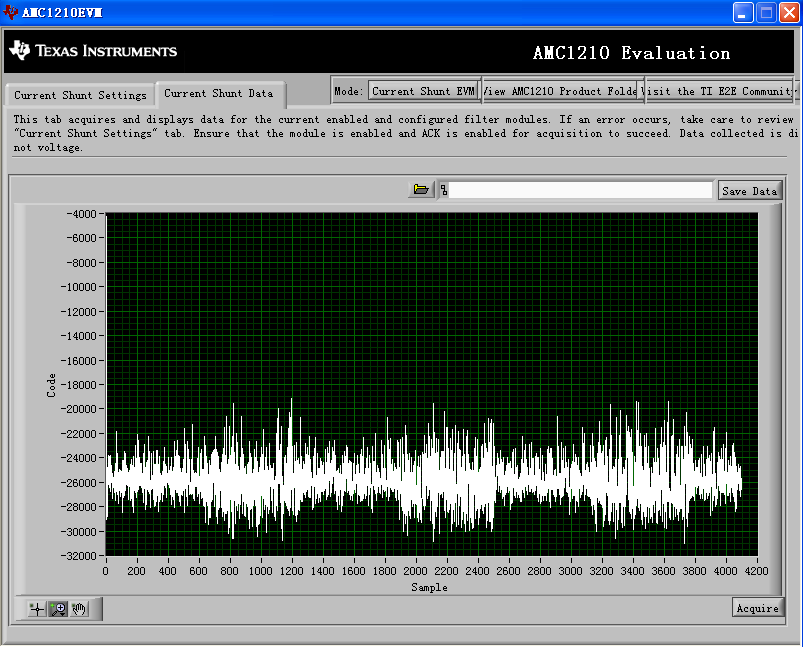
The result is this:

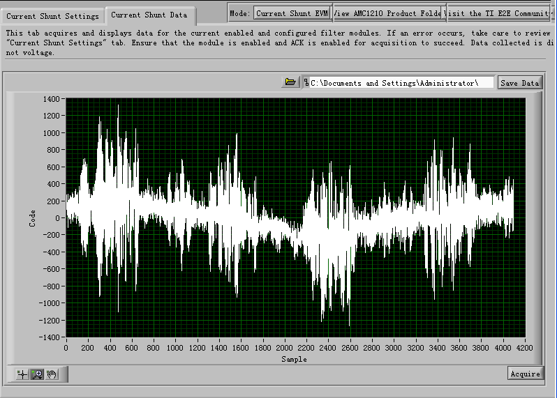
I am very puzzled why there is such an image. According to my understanding, it should be a sine wave output. Is it a problem with my settings, or something else?

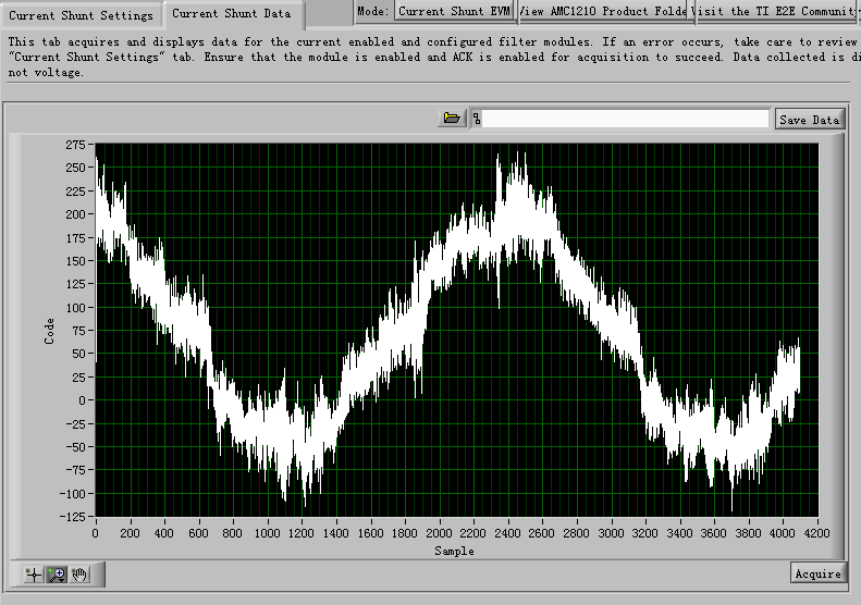
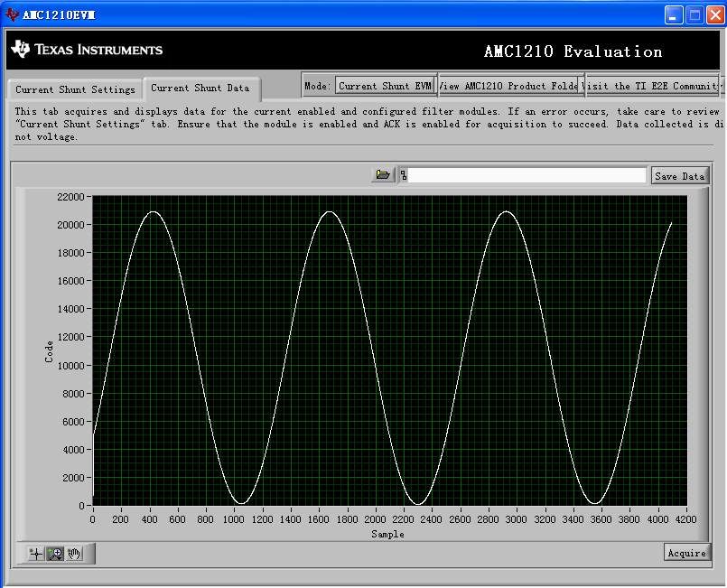
I also tested the output graph of sin3:

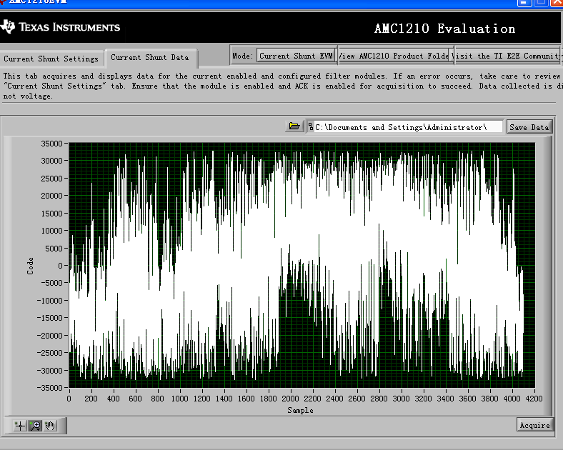
May I ask what is the problem? Can you give me some suggestions, thank you!

  • Hi Zhenfxin,

    Three things to look at.  The AMC1305 only works in mode 00.  Also the OSR is the entered value +1, so your 128 is actually 129 - not sure if that was your intention or not.  Also, with 16-bit data, you need to add a shift, please review the AMC1210 datasheet.  You can also try this with 32-bit data to see if that cleans up the signal.

  • Hi Tom,

    Thank you for your help, it's better after setting up.But still a bit confused

    My settings are as follows

    Input is 200mv, 5Mhz sine wave,

    The output is still abnormal. What is the reason?I set the shift data, when it is 10, the output is as follows

    So how should shift data choose? What factors will it affect?

    At the same time, I also have doubts about the calculation of the code:

    How should I judge the conversion accuracy of sin1, sin2, and sin3? Does the code have any correspondence? How to get its ENOB from the picture?

    Thanks!

    Regards

  • Hi Zhengxin,

    I'm curious to know what operating system you are running the AMC1210MB-EVM with, we have another poster who is trying to run it on Win10 and is having trouble.

    Shifting only impacts which significant bits you pull from the filter.  It has to do with DC gain of the filter which is OSR^Sinc Order.  The AMC1210 datasheet shows an example of a  Sinc3 filter with OSR of 256.  That is a gain of 16,777,216 (256^3), which is 25 bits. Shifting by 9 (not 10) gets you the most significant 16 bits.

  • Hi Tom,

    Actually ,I am using AMC1210 software in WIN XP system.

    As you said, My settings are as follows and I got this result.( My input is sine wave)

    This result also puzzled me, did I make a mistake? I also set 32bit,

    Why is the output a constant value? What do 32bit and 16bit codes represent? How to calculate?

    Can you give me some suggestions?

    Thanks a lot!

    Regards,

    zhengxin

  • Hi Zhengxin,

    In your initial post, you said you were working with a 5MHz sine wave, I thought that might be a typo, so I didn't comment on it.  In your picture above, the sine wave looks to have a 1uS period, or frequency of 1MHz.  You need to consider the actual sampling rate of the filter here.  With a 20MHz clock and 256OSR a you are looking at a sample rate of ~78kHz.  Slow down the signal generator to ~10kHz and see if you can see a waveform.  Unfortunately the author of the AMC1210MB-EVM Software did not include and analysis functions in the code.  You could export the data to MatLab perhaps if you needs to do analysis.

  • Hi Tom,

    Thanks for your reply, I can read the waveform after adjusting the frequency of the signal generator

    But now there is a new problem. When I use AMC3306EMV to test, I still can't read the waveform. But my settings are consistent with AMC1305EVM

    The same situation in AMC1305:

    Do you have any advice?

    Regards,

    zhengxin

  • Hi Zhengxin,

    Check the CLK and DATA as it reaches the AMC1210.  The AMC1305 and AMC3306 use different clock edges to strobe data into the filter, I suspect you are not meeting the setup and hold times of the AMC1210 with the AMC3306 device.  You may need to invert the clock before returning it to the AMC1210 filter when using the AMC3306.

  • Hi Tom,

    I don’t quite understand "You may need to invert the clock before returning it to the AMC1210 filter when using the AMC3306"

    Is there any difference between CLKIN of AMC1305 and AMC3306?

    Regards,

    zhengxin

  • Compare AMC1305 Figure 1 to AMC3306 figure 6-1 and look at DOUT relative to CLKIN.  Data (from the filter perspective) is valid on the rising clock edge of the AMC1210 (Figure 1, Mode 0) which is how the AMC1305 transmits the bitstream.  The AMC3306 is opposite from the AMC1305.

  • Hi Tom,

    I have some doubts. I use the clock output from AMC1210 and connect to AMC1305 and AMC3306. As you said, I think AMC1305 and AMC1210 are the same, but I think it should be triggered by the falling edge of the clock. Why does the data sheet state that it is triggered by the rising edge? Did I misunderstand?

    Another question, if I want to implement AMC3306+AMC1210, do I need to use an external clock, connect the clock to AMC3306, and then input the clock to AMC1210 through an inverter? Or is there a better solution?
    My customer is using F28377S, its Sigma Delta Filter Module clock looks the same as AMC1210 settings, if I want to use AMC3306, is there any convenient way?

    ( modulator mode of F28377S)

    Thank you for your support!

    Regards,

    Tom

  • Which datasheet are you referring to?  The AMC1210 expects valid data on a rising CLK edge.  The AMC1305 provides valid data on a rising CLK edge, and the AMC3306 (AMC1306 as well) provides valid data on a falling CLK edge.  Ultimately you need to make sure the setup and hold times of the digital filter are met relative to the clock edge it needs to see for a valid data signal.

  • According to the understanding, as shown in Figure 1 of AMC1210, when the CLK falling edge, the signal is sampled and held. In the data sheet of the AMC3306, I feel that it is triggered by the rising edge of CLK. Where did i go wrong?

    I think I may have misunderstood some information. But the important thing is that I know that AMC1305 and AMC1210 are the same, and AMC3306 and AMC1210 are different. So how should I use AMC3306 with AMC1210? Is there any easy way?
    (The Sigma Delta Filter Module in the C2000 used by my customer is consistent with AMC1210. I am wondering how to use AMC3306)

    (Modulator of  C2000)

    Regards,

    ZHENGXIN

  • Hi Zhengxin,

    You are not reading the AMC1210 datasheet correctly.  The dashed line in that figure tells you that the data needs to be valid for tSU time before and remain valid for tHD time after the rising CLK edge.  What you have highlighted in figure 6.1 from the AMC3306 datasheet is hold time and delay time until the next bit in the DOUT is valid.  The hold time of the AMC3306 is 3.5nS (min) when the AMC1210 is expecting 5nS minimum.

    So, using a 20MHz clock and assuming you have a 50/50 duty cycle, after the rising clock edge you have valid data for at least 3nS and the next bit is valid in no more than 15nS.  If you go ahead and invert the clock feeding the AMC3306 and send that back to the SDFM, you should have ample setup and hold times to satisfy the filter module requirements. Talk to your local C2K team, this functionality is built into the DSP I believe.

  • Hi Tom,

    I probably understand what you mean, and I am still a little confused

    As your picture shows, whether Th and Td will occur on the same rising edge. The data is in the setting stage within Td time, so does the rising and falling edges before and after the red area of Dout (as shown in the figure) have any meaning

    Regards,

    ZHENGXIN

  • Hi Zhengxin,

    For the AMC3306, yes - tH and tD are relative to the same rising clock edge.  The area you marked in red is the area of uncertainty between output data transition states.  You have 3nS minimum hold time for valid data and 15nS maximum for the next valid data output from the rising CLK edge.  The 12nS in between the two is ??? - or indeterminate.  You cannot guarantee there will be data valid in that region.