This thread has been locked.

If you have a related question, please click the "Ask a related question" button in the top right corner. The newly created question will be automatically linked to this question.

AMC7834EVM: SENSE1 conversion issue

Part Number: AMC7834EVM

I seem to be having an issue with the SENSE1 input on the EVM board.  I have an input set up that will generate a 0-200mV signal, but the reading I'm getting on SENSE1 continuously bounces between 0 and a high value.  If I connect the same circuit to another SENSE input it shows the correct value.  Is the SENSE1 input bad or is there something else I'm missing?

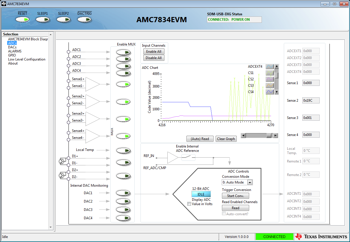
I'm including a screen shot of the evaluation interface that shows the same input connected to CS4, the blue line, then moved and connected to CS1, the light green line.  As you can see, the value seems to be fine on CS4, but when moved to CS1 it just jumps up and down.

  • Hi Eric,

    Note that the sense lines should be a differential measurement with a DC offset.  We specify a common mode of 4V minimum, so you should ensure that you are doing that. 

    Does the digital readback value jump around as much as the graph? Just want to eliminate if a software issue can cause this.

    Thanks,

    Paul

  • Paul,

    Thanks for the reply.  Yes, the readback value is jumping as well and seems to be showing the same as what the graph is showing.

    I believe that the input I'm supplying is working correctly since I can move the same wires to a different SENSE input and it shows the steady state value that I expect, this only happens when connected to SENSE1 +/-.  I currently have it biased at +5v.

    +Ric

  • Given that you are having other problems with the other input, I wonder if somehow this pin was damaged or is floating.  You could inspect the solder joint and see if there is a dry/cracked lead or pad.

    Please shoot me an email at frost@ti.com and I will sample you a replacement.

    Thanks,
    Paul

  • Paul,

    I just sent you an e-mail, I appreciate your help.

    I saw that my other thread was merged with this one.  I believe there is still some information I'm missing regarding resetting the chip after the ADC sets the output to zero.

    Thanks,

    Ric

  • Hi Ric,

    The device should not require a reset.  I think the behavior you are seeing has something to do with the potential damage on the CS1 pins.

    Thanks,

    Paul

  • Paul,

    It took me a while to get back to this, but I have connected the new board up to my system and the CS1 input is working fine now.  I'm actually using CS1 and CS2.  

    I still have the issue where if the signal being sensed by CS1 goes above the maximum for a few seconds, then both values for CS1 and CS1 will go to zero.  I also noticed that the Power Mode, which I had set to 2 also goes to zero.  I can send commands that perform my "initial" configuration and the inputs will start working again.  I've checked the alarm register, but it seems there are no bits set there indicating an alarm.  I'm thinking of monitoring the Power Mode, but it seems there should be another way of doing this.  Do you have any ideas what may be happening?

    Thanks,

    Ric

  • Hi Ric,

    Seems like something is resetting the device.  Do you have any supplies that could be intermittently disconnecting when you this test?

    Thanks,

    Paul

  • Paul,

    Thanks!  I believe you must be correct.  I'm pulling the power for my small resistor circuit from the 5v VCC on the board.  If the voltage goes too high one of the green LEDs on board will start to flash.  It looks like I'm causing my own problem!  I appreciate your help troubleshooting, sorry I didn't realize that myself.

    Best regards,

    Ric

  • I think as engineers, the simplest solution is always the hardest one for us to get to! :)