Other Parts Discussed in Thread: DAC0802, , LM324
Hi,
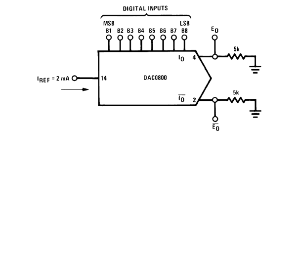
I am trying to debug a situation where I re-created a circuit fundamentally identical to the one listed in your document/datasheet SNAS538C ( DAC0800, DAC0802) page 10 figure 23 with the following modifications :
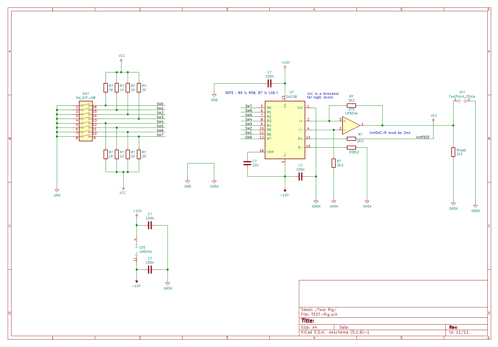
- the V+ is 12V - the V- is -12V
- the opAMP is an LM324 ( powered as well at +12V -12V )
- the Vref first been tried at 8.0V
- the resistors, to meet the 2mA requirement been changed from 5KOhm to 4KOhm
- Input are TTL level guaranteed to match the requirements ( i.e. Voh > 2.0 V and Vol < 0.8 V)
- VLC been set to 0V ( for TTL input )
In those conditions I can't make the DAC work at all, no matter the digital inputs there appear to be absolutely no variation in the output ( which seems to be stuck at 11.89 V about ).
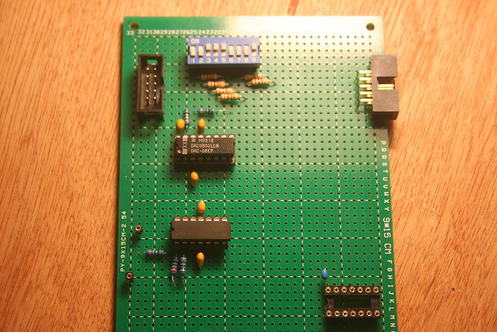
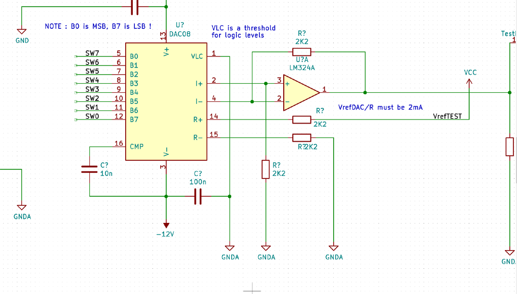
Then I tried a "test rig" to try to nail down the problem ( see attached schematic , VCC is set to 5V , so Vref is 5V ) but then again the DAC in those conditions seems simply not work at all.
I can't figure out why.
At this point some things are not very clear in the Datasheet, all the examples seems to show that Vref is always set at +0V, can it be set at any different value ?
Is that a VrefMin / VrefMax value that has to be respected and/or some relationships between Vref and Vsupply ?
The datasheet seems to mention the DAC0800 can work with a supply from -/+ 4.5 V up to a max of +/- 18V so I assume there should be no problems in working with +/- 12V ?
Thanks in advance for any help, it's really puzzling me.
Cheers. Ivan Z.


