This thread has been locked.

If you have a related question, please click the "Ask a related question" button in the top right corner. The newly created question will be automatically linked to this question.

ADS131A04EVM: Problems with noise on the input of the device and voltage divider wont work with the device.

Part Number: ADS131A04EVM

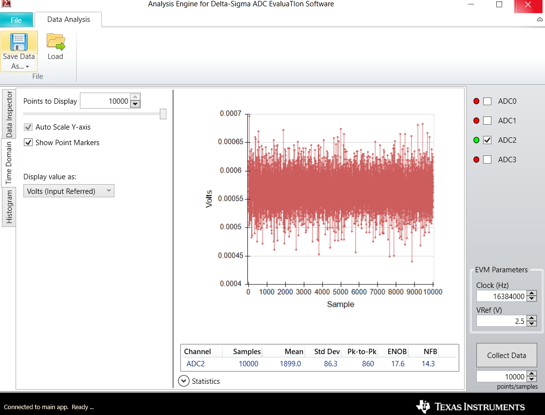
I have been testing with this device and I have come across a problem with the noise on the input of the ADC, which is about 0.270 mV. Also with the use of the voltage divider I get a weird offset and it is not working properly. The Input signal I use is with the function generator, which is a 50 Hz 20 mVpp signal.

  • Hello Sebahaddin,

    Thank you for your post and welcome to our forum.

    It's possible that your signal source is introducing some of this noise. Make sure that the function generator ground is shared with the EVM ground with a solid, direct connection. In addition, if the signal source output and your power line frequencies are the same, you may observe other unwanted noise anomalies if the setup is not properly grounded and shielded.

    Can you share a schematic of the voltage divider circuit that is connected to the EVM? Please also share some oscilloscope captures of the input signal and a plot of the ADC output with applied register settings.

    Regards,

  • The schematic for the voltage divider is this:

    If I want to use for example J6, do I have to short the ground (pin 2) and the minus (pin 1) input together ? Do I have to do anything with pin 2 of J6 and J10 when connecting CT to it.

  • I have checked the input noise of the ADS131A04EVM by shorting the inputs + and the - from J7 short. I get values around 900-950, which translates to 900 * (FSR)/(2^24). The Vref in my case is 2.442 V so the FSR is 4.884 V which results in 900 * (4.884/2^24) = 262 uV noise.

    The register settings are: 

    I am using 42667 SPS. But, actually I wanted to use the 64.000 SPS but that didn't work well, led D2 goes off when using 64k SPS.

    The voltage divider adc output is this, when applying 20 mVpp and 50 Hz on the input of the ADS131A04EVM, changing the frequency didn't change the results much:

    Kind regards,

    Sebahaddin Yilmazer

  • Hi Sebahaddin,

    It looks like there is a mistake in the script register command descriptions. The value written to 0Eh (0x2C) corresponds to OSR = 96, which gives you a data rate of 42.667 kSPS.

    The typical noise for this configuration, measured with shorted inputs, is about 13.85 uVrms, which equates to 91.41 uVpp. These measurements are taken in a shielded environment with the ADC input pins directly shorted together and biased to a mid-supply common-mode voltage. The additional noise that you've observed could be explained by the lack of an established common-mode and additional noise coupling along the external signal path.

    In your voltage divider circuit, what is the negative channel input connected to (J7[2])? Remember that the signal source ground must be shared with the EVM ground.

    Regards,

  • Hello Ryan,

    Is the convertation from 13.85 uVrms done using the analog supply voltage of 3.3 V: 13.85 * 3.3 * 2 = 91.41 uVpp

    In the voltage divider circuit I have connected a coax cable with two clippers on it, these clippers are connected to the IN+ and the IN- of J7. So the negative side or the low side is connected to pin 2 of J7.

    This is the noise when shorting pin 1 and 3 of J9:

    This is the noise when applying 100mV DC :

    Does it work to filter out the noise or smooth the noise in the program like Matlab with these sampled data or does that affect the accuracy too much ?

    Regards,

    Sebahaddin